3 - 34
IPN 074-505-P1E
IC6 Operating Manual
3.6 Special Features
The IC6 has several special features to enhance the performance of the
instrument.
3.6.1 Crystal Switching
The IC6 offers a choice of Single, XtalTwo (CrystalTwo
®
), XtalSix (CrystalSix
®
),
Xtal12 (Crystal12
®
), or Generic sensors. The CrystalTwo, CrystalSix, Crystal12,
and Generic sensors provide one or more backup crystals in case a crystal fails
during deposition. Sensor types are specified on the Sensors screen.
The XtalTwo option requires the 779-220-G1 or 779-220-G2 XTAL2 Switch. The
XTAL2 Switch is connected to any sensor input through an XIU package. A Dual
Sensor head can also be used by configuring it as two single sensors with the
second Dual Head Sensor configured as Backup Sensor by using an XIU in place
of the 779-220-Gx XTAL 2 Switch. The normally uncovered crystal is connected to
Sensor x, the backup crystal normally covered by the shutter is connected to
Sensor y (where y is any available sensor channel). Sensor y is configured as
Backup Sensor for Sensor x in the Sensor page of the Material screen and must
have a shutter output assigned in the Sensor page of the Sensor screen. The
manual Switch Crystal function is not available in this configuration.To calibrate the
Backup Sensor, temporarily set it to be the Sensor.
All multi-position and shuttered sensors require the Pneumatic Actuator Control
Valve, part number 750-420-G1, and a feedthrough with an air tube.
A crystal switch will automatically occur when:
The IC6 is configured for a XtalTwo (CrystalTwo) sensor type, a layer is
STARTed or running and there is another good crystal available when the
active crystal fails.
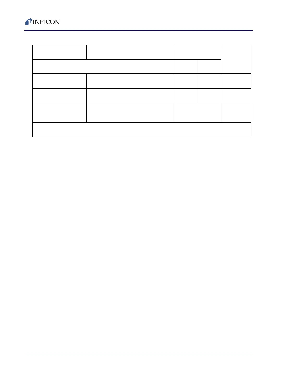
19. IDLE RAMP Source changing to Idle Power level. [Idle
Ramp Time, Idle Power]
Inactive Inactive 18
20. IDLE Source resting at Idle Power; will accept a
START command.
Inactive Inactive 19
21. SUSPEND (layer) The respective layer’s source output is set
to zero power. The layer’s display is frozen
at the last rate and thickness values.
Inactive Inactive 20
NOTE: In STOP or SUSPEND, the IC6 will accept a START provided a valid crystal is available for the layer(s)
being started.
Table 3-2 State descriptions (continued)
STATE CONDITION RELAY CONTACT
STATUS
REMOTE
COMM
ENCODES
Source
Shutter
Sensor
Shutter