Installation 23
iina74e 02.fm technical handbook(1408)
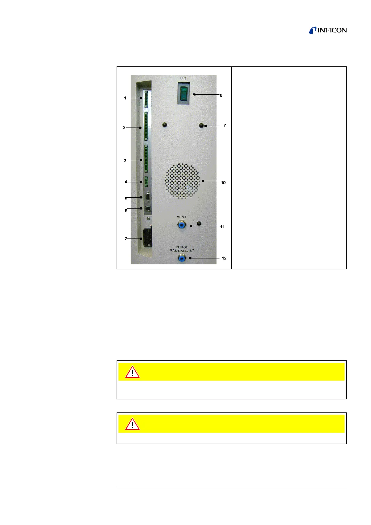
2.3.2 Connections for the Data Acquisition Systems
Tipp The sockets: Accessories, Digital Out, Digital In and Recorder have pin 1
on top. The pin numbers are counted downwards. The socket 2 and 3 are
coded mechanically to avoid a confusion with the counter plug. For the
connection with the counter plug (set of plugs 20099024) remove the
plastic pins at the plug, accordingly the plug fits the socket.
Notice: The connections for external devices are safely separated from the mains
and safe low voltage.
1. Accessories
2. Digital Out
3. Digital In
4. Recorder
5. RS232
6. Remote Control RC1000 / Wireless
Transmitter
7. Mains Socket
8. Mains Switch
9. Hole to mount cable hooks.
10. Speaker
11. Vent
12. Purge
Fig. 2-6 Connections
The electronic of the device can be destroyed. So just connect devices to the leak
detector that are separated from the mains.
Only connect devices that don’t exceed 25V AC/1A