46 Description of the Menu
iina74e 06.fm technical handbook(1408)
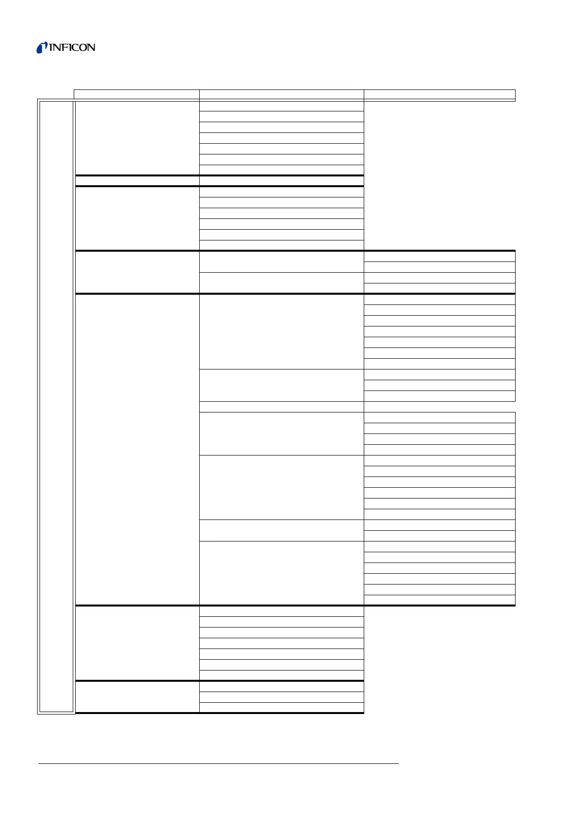
Fig. 6-2: Menu Structure overview
1. Level 2. Level 3. Level
Main Menu
View (See 6.2)
Scale linear/logarithmic
Display-range auto/manual
Time axis
Contrast
Background in Stand-by
Decimal places
Lower display limit
Mode (See 6.3) Sniff/Vacuum
Trigger & Alarms (See 6.4)
Trigger Level 1
Trigger Level 2
Volume
Units
Alarm delay
Audio alarm type
Calibration (See 6.5)
internal
manual
automatic
external
Edit leakrate
Start
Settings (See 6.6)
Vacuum settings
Automatic purge
Vent delay
HYDRO•S
Vacuum ranges
Leak rate internal test leak
Machine factor
Booster TMP mode
Zero & Background
Background Suppression
Calculate Inlet Area Background
Zero
Mass
Interfaces
Control Location
Recorder output
RS232 Protocol
Scaling Recorder Output
Miscellaneous
Time&Date
Language
Leak rate filter
Mains Frequency
Service interval exhaust filter
Service message exhaust filter
Parameter save / load
Save parameter set
Load parameter set
Monitoring functions
Calibration request
Particle Protection
Contamination protection
Pressure limits for vacuum ranges
Pressure limits for sniff mode
Maximum evacuation time
Information (See 6.7)
View settings
View internal data
Vacuum diagram
View error list
Calibration history
Calibration factors
Service
Access Control (See 6.8)
Access to CAL function
Change Device PIN
Change Menu-PIN