Appendix. Parameter Table
- 319 -
Parameter
No.
Parameter Name Setting Range Default Property Page
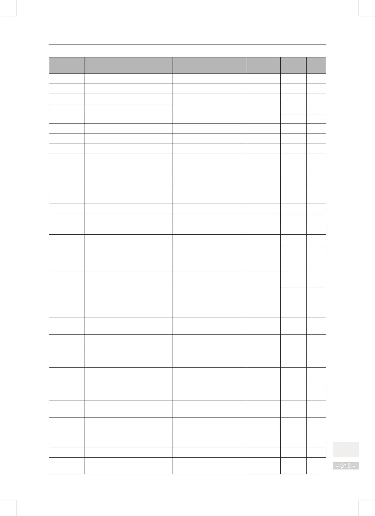
F9-29 Bus voltage upon 2nd fault - - ● -
F9-30 DI state upon 2nd fault - - ● -
F9-31 DO state upon 2nd fault - - ● -
F9-32 AC drive state upon 2nd fault - - ● -
F9-33 Power-on time upon 2nd fault - - ● -
F9-34 Running time upon 2nd fault - - ● -
F9-37 Frequency upon 1st fault - - ● -
F9-38 Current upon 1st fault - - ● -
F9-39 Bus voltage upon 1st fault - - ● -
F9-40 DI state upon 1st fault - - ● -
F9-41 DO state upon 1st fault - - ● -
F9-42 AC drive state upon 1st fault - - ● -
F9-43 Power-on time upon 1st fault - - ● -
F9-44 Running time upon 1st fault - - ● -
F9-47 Fault protection action selection 1 00000 to 22222 00000
☆
1
4
1
F9-48 Fault protection action selection 2 00000 to 11111 00000
☆
1
4
1
F9-49 Fault protection action selection 3 00000 to 22222 00000
☆
1
4
2
F9-50 Fault protection action selection 4 00000 to 22222 00000
☆
1
4
2
F9-54 Frequency selection for continuing
to run upon fault
0 to 4 0
☆
1
4
2
F9-55 Backup frequency upon fault 0.0% to 100.0% (max.
frequency)
100.0%
☆
1
4
2
F9-56 Type of motor temperature sensor 0: No temperature sensor
1: PT100
2: PT1000
0
☆
1
4
3
F9-57 Motor overheat protection
threshold
0°C to 200°C 110°C
☆
1
4
3
F9-58 Motor overheat pre-warning
threshold
0°C to 200°C 90°C
☆
1
4
3
F9-59 Power dip ride-through function
selection
0 to 2 0
★
1
4
4
F9-60 Threshold of power dip ride-
through function disabled
80% to 100% 85%
★
1
4
4
F9-61 Judging time of bus voltage
recovering from power dip
0.0s to 100.0s 0.5s
★
1
4
4
F9-62 Threshold of power dip ride-
through function enabled
60% to 100% 80%
★
1
4
4
F9-63 Load lost protection 0: Disabled
1: Enabled
0
☆
1
4
4
F9-64 Load lost detection level 0.0% to 100.0% 10.0%
☆
1
4
4
F9-65 Load lost detection time 0.0s to 60.0s 1.0s
☆
1
4
4
F9-67 Overspeed detection level 0.0% to 50.0% (max.
frequency)
20.0%
☆
1
4
5

 Loading...