Product Information
‑16‑
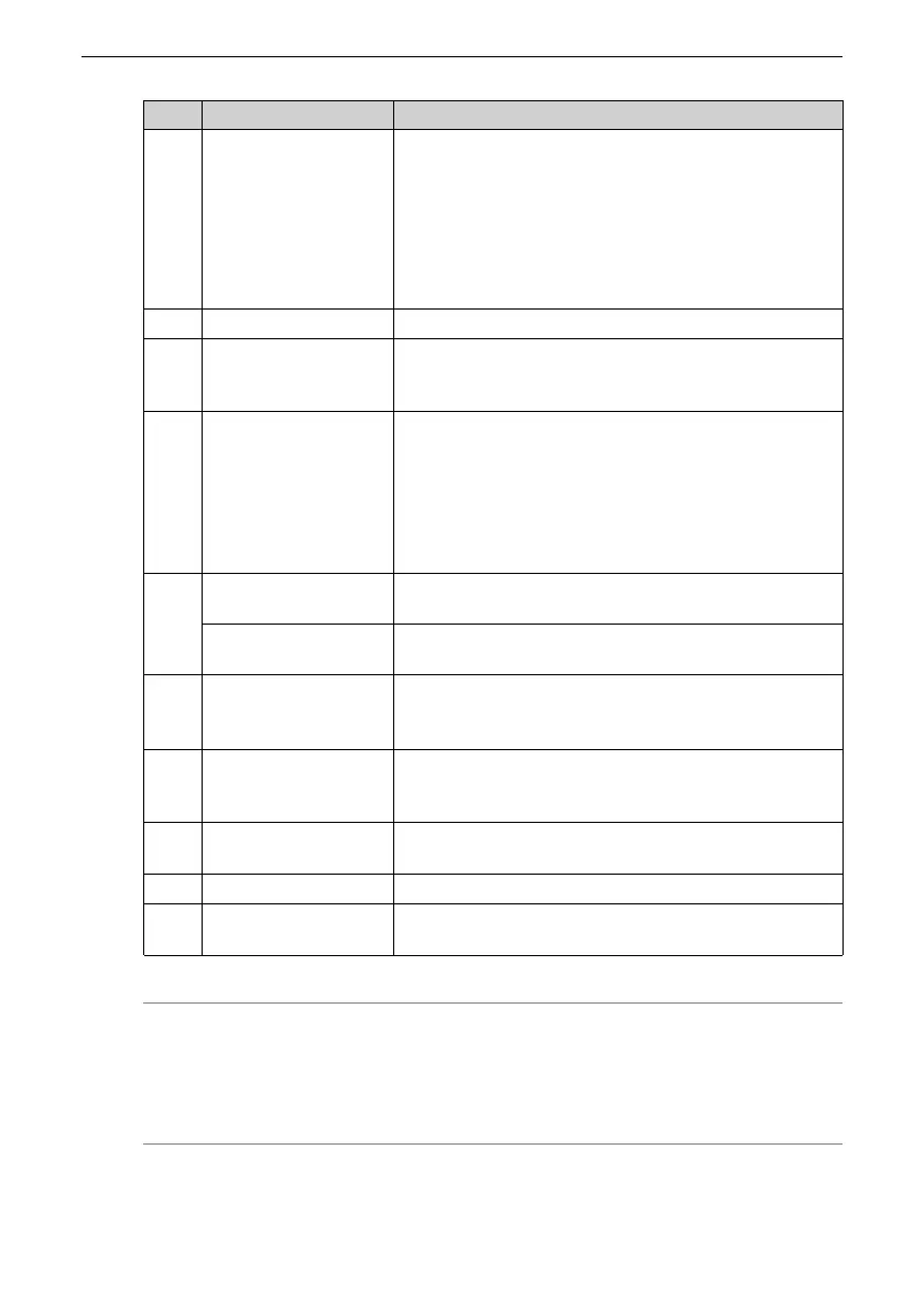
No. Name
Description
3
Keys
MODE: Used to switch parameters in sequence.
△: Used to increase the value of the blinking bit.
▽: Used to decrease the value of the blinking bit.
◁: Used to shift the blinking bit leftwards.
(Hold down: Turning to the next page when the
displayed number exceeds five digits)
SET: Used to save modifications and enter the next
menu.
4
CN1 (control terminal)
Used by reference input signals and other I/O signals.
5
CN2 (terminal for
connecting the
encoder)
Connected to the motor encoder terminal.
6
CHARGE (bus voltage
indicator)
Used to indicate the electric charge is present in the bus
capacitor. When this indicator lights up, it indicates the
electric charge may be still present in the internal
capacitor of the servo drive even though the main circuit
power supply is switched off.
To prevent electric shock, do not touch the power supply
terminals when this indicator lights up.
7
L1, L2 (power input
terminals)
See the nameplate for the rated voltage class.
P⊕, NΘ (DC bus
terminals)
Used by the common DC bus for multiple servo drives.
8
P⊕, C (terminals for
connecting external
regenerative resistor)
If an external regenerative resistor is needed, connect it
between terminals P⊕ and C.
9
U, V, W (terminals for
connecting the servo
motor)
Connected to U, V, and W phases of the servo motor.
10
Motor grounding
terminal
Connected to the grounding terminal of the motor for
grounding purpose.
11
Battery location Used to hold the battery box of the absolute encoder.
12
Servo drive grounding
terminal
Connected to the grounding terminal of the power
supply for grounding purpose.
Note
The built‑in regenerative resistor or jumper bar is not available in models S1R6 and S2R8. If
an external regenerative resistor is needed for these models, connect it between terminals
P⊕ and C.

 Loading...


