Intel Desktop Board D2550DC2 Product Guide
28
Installing and Removing Memory
NOTE
To be fully com pliant wit h all applicable I ntel SDRAM m em ory specificat ions, t he
boards r equir e SO- DI MMs that support t he Serial Presence Det ect ( SPD) dat a
st ruct ure.
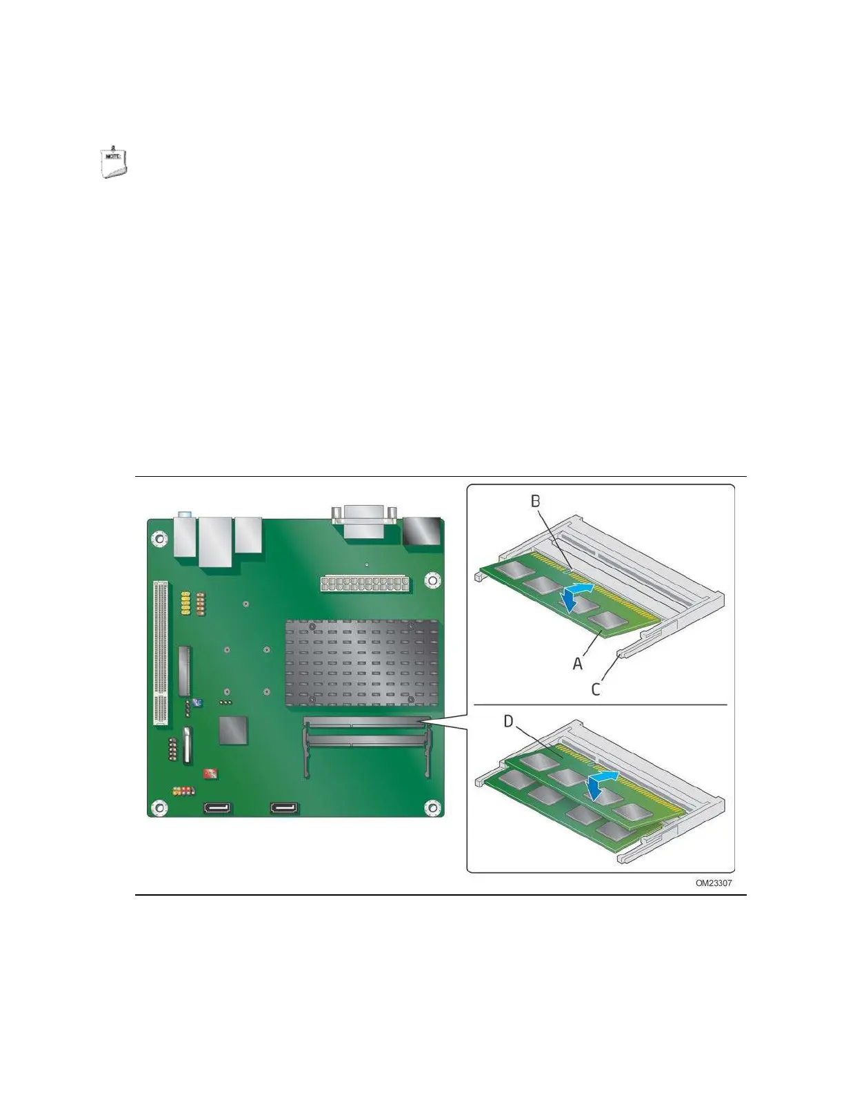
The Desktop Board has t wo 204- pin DDR3 SO- DI MM socket s t hat support up t o 4 GB
of syst em m em ory. To inst all syst em m em ory on t he Deskt op Board, see Figure 7 and
follow t hese st eps:
1. Observe t h e precaut ions in "Before You Begin" on page 23.
2. I nstall the first SO- DIMM ( Figure 7, A) in t he bot t om ( SO- DI MM 1) socket. Align
the notch in the SO- DI MM with t he key in t he socket ( Figure 7, B) , while holding
t he SO- DI MM wit h t he back edge t ilt ed slightly upwards, insert it in the socket ,
and gently push the back edge down until it snaps into t he ret ent ion arm s
( Figure 7, C).
3. I f you are installing a second SO- DI MM, r epeat St ep 2 using t he top (SO- DI MM 0)
socket ( Figure 7, D) .
Figure 7. Installing System Memory
To rem ove an SO- DI MM from a socket , gent ly spread t he socket ’s ret en t ion arm s
( Figure 7, C) t o disengage them from t he SO- DI MM.