Installing and Replacing Desktop Board Components
35
Connecting to the Front Panel USB 2.0 Headers
Befor e connect ing t o t he USB 2 .0 headers, observe t he precaut ions in " Befor e You
Begin" on page 23. See Figure 11, B and E for t he locat ion of t he USB 2.0 header s.
Table 7 and Table 8 show t he pin assignm ent s for t h e headers.
The brown USB header ( Figur e 11, B) supports a single USB port while the black USB
header ( Figure 11, E) supports two USB port s. The single USB port header is designed
to support a Flash Mem ory Drive such as the I ntel Z- U130 USB Solid- St at e Drive ( or
com pat ible device) . Refer to “ I nst alling an I nt el
®
Z-U130 USB Solid- St at e Drive or
Com patible Device” on page 32 for m or e infor m at ion.
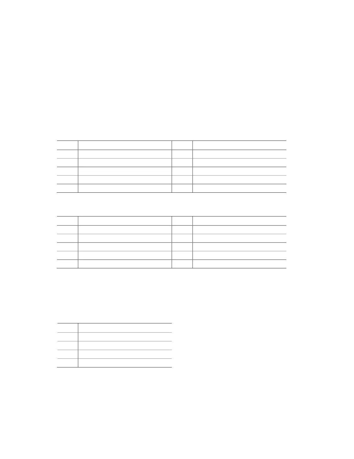
Table 7. Front Panel USB Header
Pin Signal Name Pin Signal Name
1
+ 5 VDC
2
+ 5 VDC
3
D-
4
D-
5
D+
6
D+
Ground
Ground
9
KEY (no pin)
10
No Connect
Table 8. Front Panel USB Header with Intel Z-U130 USB Solid-State Drive or
Compatible Device Support
Pin Signal Name Pin Signal Name
1
+ 5 VDC
2
No Connect
D-
No Connect
5
D+
6
No Connect
7
Ground
8
No Connect
9
KEY (no pin)
10
LED#
Connecting to the Piezoelectric Speaker Header
Figure 11, C show s t he locat ion of t he piezoelect ric speaker header. Table 9 shows the
pin assignm ents for t he piezoelect ric speaker header .
Table 9. Piezoelectric Speaker Header
Pin Signal Name