Intel Desktop Board D2550DC2 Product Guide
36
Connecting to the Front Panel Header
Befor e connect ing t o t he front pan el header, observe the pr ecautions in "Before You
Begin" on page 23. See Figure 11, D for t he location of t he front panel header.
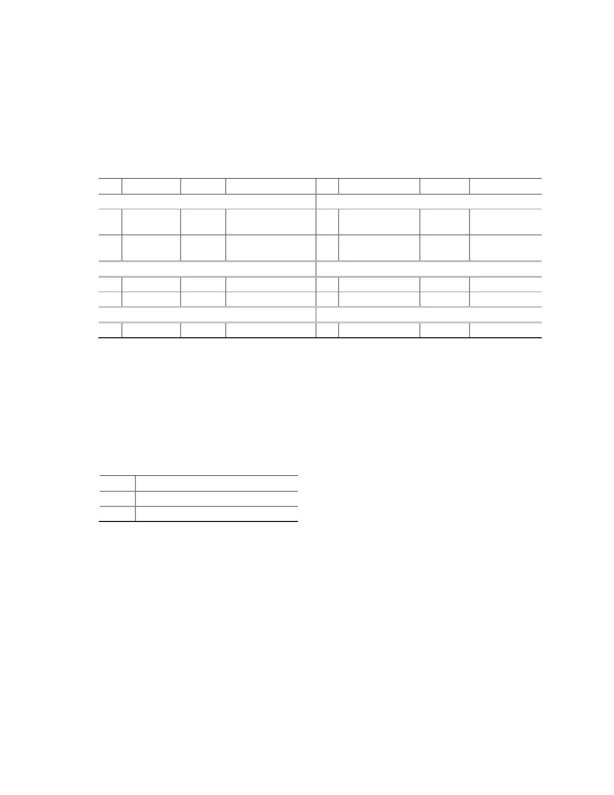
Table 10 shows the pin assignm ents for t he front panel header.
Table 10. Front Panel Header
Pin Signal In/Out Description Pin Signal In/Out Description
Hard Drive Activity LED Power LED
1 HD_PWR Out
Hard disk LED pull-
up ( 330 Ω) t o + 5 V
2 HDR_BLNK_GRN Out
Front panel
green LED
3 HDA# Out
Hard disk act ive
LED
4 HDR_BLNK_YEL Out
Front panel
yellow LED
Reset Switch On/Off Switch
5 Ground Ground 6 SWI TCH_ON# I n Power sw it ch
7 FP_RESET# I n Reset switch 8 Ground Ground
Power Not Connected
9 + 5 V Power 10 N/ C No pin
Connecting to the Front Panel Wireless Activity LED
Header
Befor e connect ing t o t he front pan el wireless act ivit y LED header, observ e t he
precaut ions in "Befor e You Begin" on page 23. See Figure 11, F for t he locat ion of t he
front panel wireless act ivity LED header.
Table 11 shows t he pin assignm ent s for the front panel wireless act ivity LED h eader.
Table 11. Front Panel Wireless Activity LED Header
Pin Signal Name
1 Ground
2 MI NI CARD_WLAN#