Intel® Server Board S2600IP and Intel® Workstation Board W2600CR TPSConnector/Header Locations and Pin-outs
Revision 1.1 91
Intel order number G34153-003
cards that need them. Available power to each of these connectors is limited by the amount of
power provided by the power supply and the total power draw for the rest of the system. A
power budget for the complete system should be performed to determine how much
supplemental power is available to support any high power add-in cards.
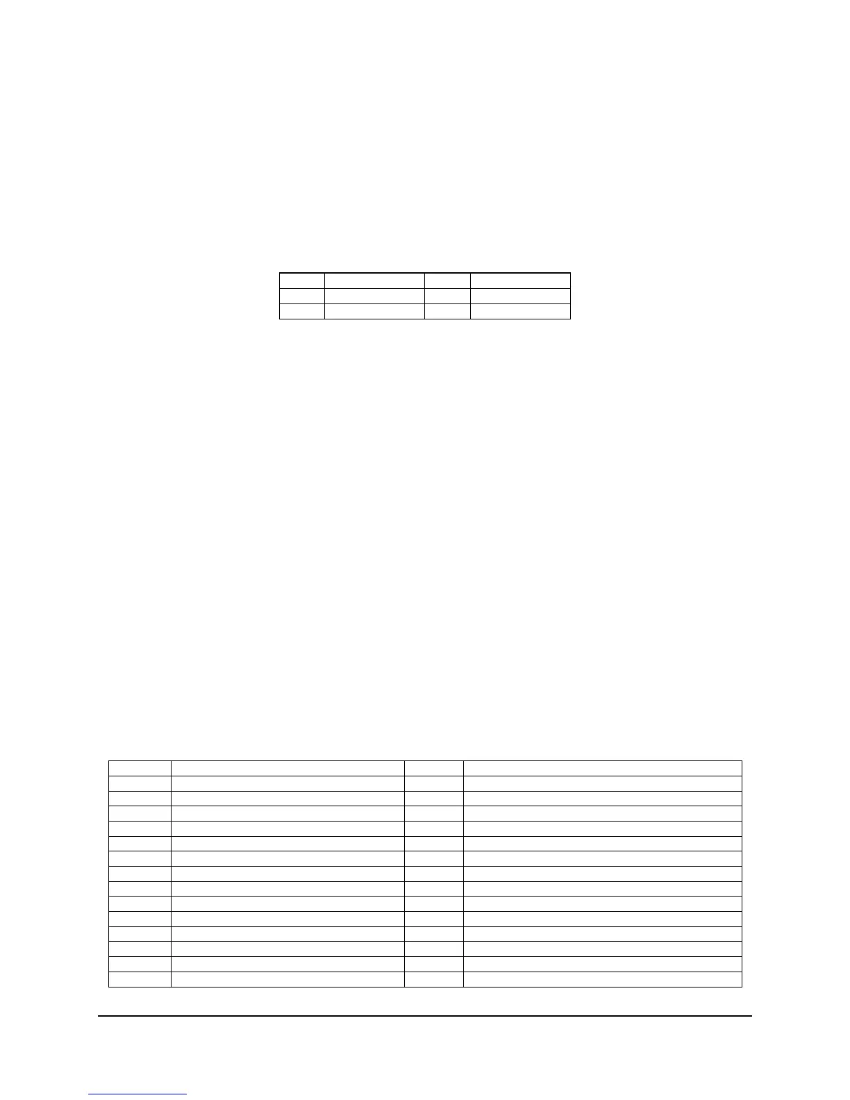
Each connector is labeled as “OPT_12V_PWR” on the server board. The following table
provides the pin-out for both connectors.
Table 32. Add-in Slot Power Pin-input ("OPT_12V_PWR")
6.2 Front Panel Header and Connectors
The server board includes several connectors that provide various possible front panel options.
This section provides a functional description and pin-out for each connector.
6.2.1 Front Panel Header
Included on the left edge of the server board is a 30-pin header consists of a 24-pin SSI
compatible front panel header and a 4-pin header to support optional NIC3/4 LEDs. The 24-pin
SSI front panel header provides various front panel features including:
Power/Sleep Button
System ID Button
NMI Button
NIC Activity LEDs
Hard Drive Activity LEDs
System Status LED
System ID LED
The following table provides the pin-out for this 30-pin header.
Table 33. Front Panel Header Pin-out
FP_LED_STATUS_GREEN_BUF_N
FP_LED_STATUS_AMBER_BUF_N
LED_NIC_LINK0_LNKUP_BUF_N
LED_NIC_LINK1_LNKUP_BUF_N