Design and Environmental SpecificationsIntel® Server Board S2600IP and Intel® Workstation Board W2600CR TPS
Revision 1.1
Intel order number G34153-003
9.4.11 Soft Starting
The Power Supply shall contain control circuit which provides monotonic soft start for its outputs
without overstress of the AC line or any power supply components at any specified AC line or
load conditions.
9.4.12 Zero Load Stability Requirements
When the power subsystem operates in a no load condition, it does not need to meet the output
regulation specification, but it must operate without any tripping of over-voltage or other fault
circuitry. When the power subsystem is subsequently loaded, it must begin to regulate and
source current without fault.
9.4.13 Ripple/Noise
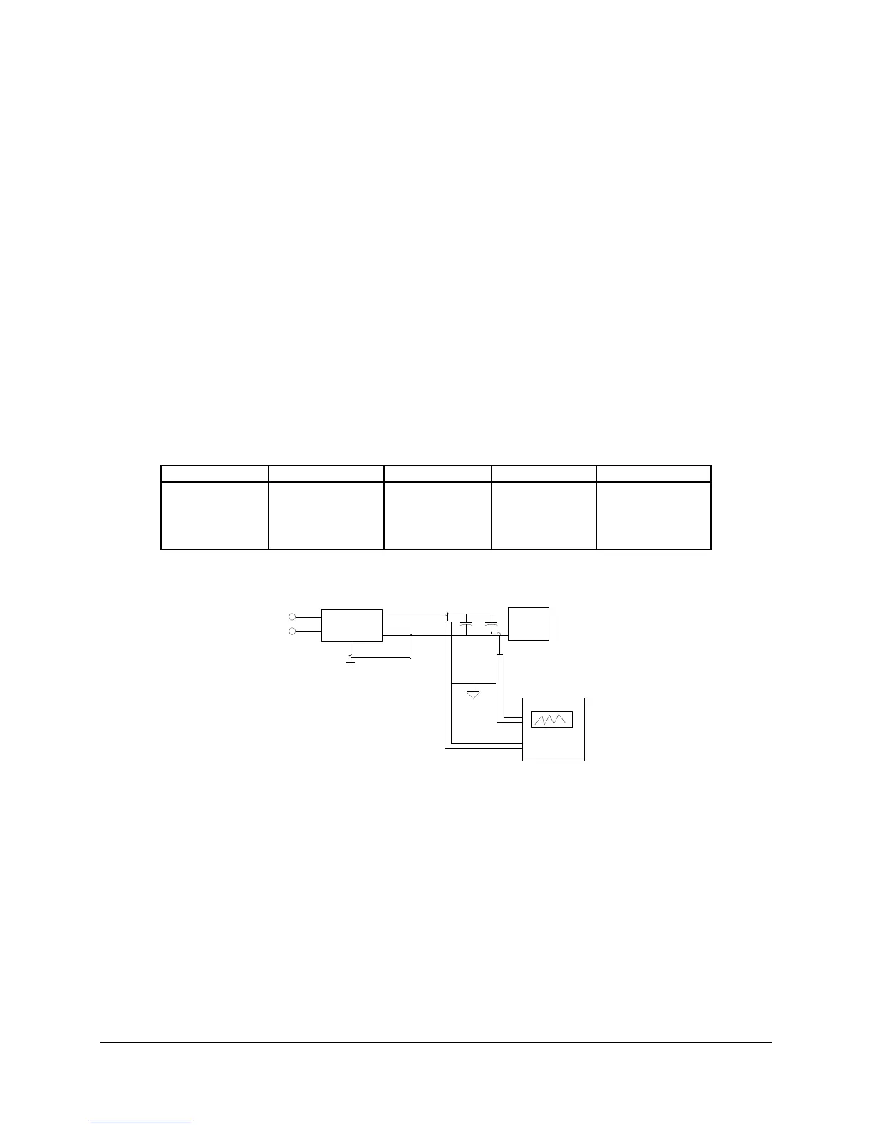
The maximum allowed ripple/noise output of the power supply is defined in the table below. This
is measured over a bandwidth of 10Hz to 20MHz at the power supply output connectors. A
10F tantalum capacitor in parallel with a 0.1F ceramic capacitor is placed at the point of
measurement.
Table 68. Ripples and Noise
The test set-up is shown below.
AC HOT
POWER SUPPLY
AC NEUTRAL
V
OUT
RETURN
V
AC GROUND
LOAD
SCOPE
LOAD MUST BE
ISOLATED FROM
THE GROUND OF
THE POWER
SUPPLY
10uF
.1uF
GENERAL NOTES:
1. LOAD THE OUTPUT WITH ITS MINIMUM
LOAD CURRENT.
2. CONNECT THE PROBES AS SHOWN.
3. REPEAT THE MEASUREMENTS WITH THE
MAXIMUM LOAD ON THE OUTPUT.
SCOPE NOTE:
USE A TEKTRONIX 7834 OSCILLOSCOPE WITH 7A13 AND
DIFFERENTIAL PROBE P6055 OR EQUIVALENT.
Figure 33. Differential Noise test setup
Note:
When performing this test, the probe clips and capacitors should be located close to the load.
9.4.14 Timing Requirements
These are the timing requirements for the power supply operation. The output voltages must
rise from 10% to within regulation limits (T
vout_rise
) within 2 to 50ms, except for 5VSB - it is
allowed to rise from 1 to 25ms. The +3.3V, +5V and +12V1,+12V2 ,+12V3 output voltages
should start to rise approximately at the same time. All outputs must rise monotonically.
Each output voltage shall reach regulation within 50ms (T
vout_on
) of each other during turn on of
the power supply. Each output voltage shall fall out of regulation within 400ms (T
vout_off
) of each