Intel® Server Board S5500WB TPS Configuration Jumpers
Revision 1.3
Intel order number E53971-004
49
6.1.4 Reset BIOS Configuration (J1B4)
This jumper used to be the CMOS Clear jumper. Since the previous generation, the BIOS has
moved CMOS data to the NVRAM region of the BIOS flash. The BIOS checks during boot to
determine if the data in the NVRAM needs to be set to default.
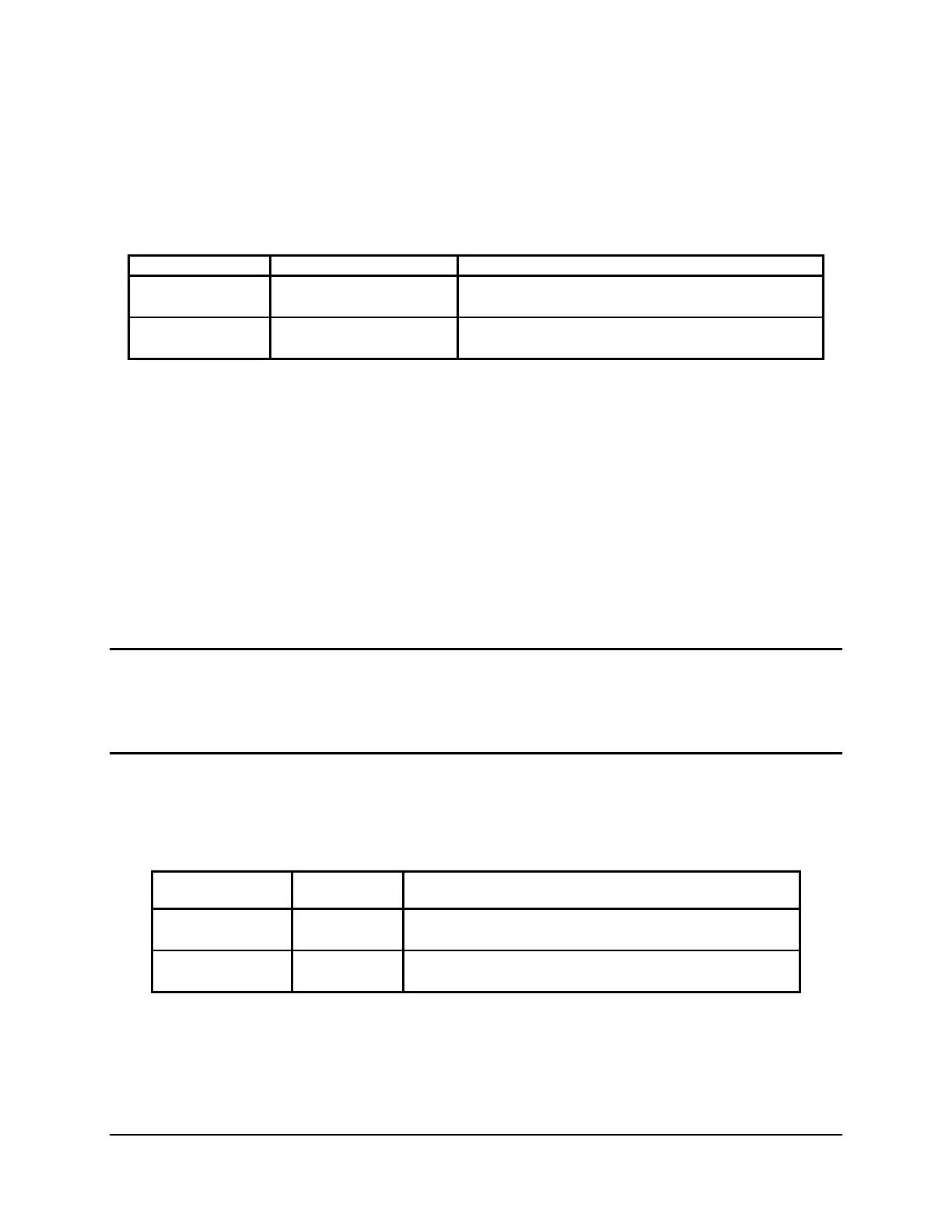
Table 20. Reset BIOS Jumper
Jumper Position Mode of Operation Note
1-2 Normal ICH10R RTCRST# pin is pulled HIGH. Default
position.
2-3 Reset BIOS
Configuration
ICH10R RTCRST# pin is pulled LOW.
6.1.4.1 Clearing the CMOS
1. Power down server. Do not unplug the power cord.
2. Open the server chassis. For instructions, see your server chassis documentation.
3. Move jumper (J1B4) from the default operating position, covering pins 1 and 2, to the
reset / clear position, covering pins 2 and 3.
4. Wait five seconds.
5. Remove AC power.
6. Move the jumper back to default position, covering pins 1 and 2.
7. Close the server chassis.
8. Power up the server.
The CMOS is now cleared and you can reset it by going into the BIOS setup.
Note: Removing AC Power before performing the CMOS Clear operation causes the system to
automatically power up and immediately power down, after the procedure is followed and AC
power is re-applied. If this happens, remove the AC power cord again, wait 30 seconds, and re-
install the AC power cord. Power-up the system and proceed to the <F2> BIOS Setup Utility to
reset the desired settings.
6.1.5 Video Master (J6A3)
Table 21. Video Master Jumper
Jumper Position
Mode of
Operation Notes
1-2 Internal Internal connector will override if both connectors are
used.
2-3 External External connector will override if both connectors are
used.
This jumper determines which video is the primary.
J6A3, 1-2 jumpered: Internal video connector is primary, but video can come out of external
video connector if you connect to it.