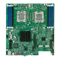
Intel® Server Board S5500WB TPS Connector / Header Locations and Pin-out
Revision 1.3
Intel order number E53971-004
65
7.4.6 Serial Port Connectors
The server board provides one external RJ-45 Serial A port (J7A1) and one internal 9-pin serial
B header (J1A2). The following tables define the pin-outs.
Table 43. External RJ-45 Serial Port A (COM1) (J7A1)
Pin Signal Name Pin Signal
1 SPA_RTS 5 SPA_RI
2 SPA_DTR 6 SPA_SIN
3 SPA_SOUT_N 7 SPA_DSR
4 GND 8 SPA_CTS
Table 44. Internal 9-pin Serial B (COM2) (J1A2)
Pin Signal Name Pin Signal Name
1 SPB_DCD 2 SPB_DSR
3 SPB_SIN_N 4 SPB_RTS
5 SPB_SOUT_N 6 SPB_CTS
7 SPB_DTR 8 SPB_RI
9 GND
7.4.7 USB Connectors
The following table details the pin-out of the external USB connectors (J7A1, J7A2) found on
the back edge of the server board and the internal connector (J9D3) centered on the right side
of the board.
Table 45. External USB Connector (J8A1, J9A1))
Pin Signal Name Description
1 +5V USB Power
2 USB_N Differential data line paired with DATAH0
3 USB_P Differential date line paired with DATAL0
4 GND Ground
Two 2x5 connectors on the server board provide an option to support an additional four USB
ports. The pin-out is the same for both of the connectors and is detailed in the following table.
Table 46. Internal USB Connector (J1C1 and J9A2)
Pin Signal Name Pin Signal Name
1 NC 2 Key Pin
3 GND 4 GND
5 USB_P 6 USB_P
7 USB_N 8 USB_N
9 +5V 10 +5V

 Loading...