Connector / Header Locations and Pin-out Intel® Server Board S5500WB TPS
Revision 1.3
Intel order number E53971-004
54
If this switch is used while the system power is still applied, then the main power rail regulators
is disabled first, then the main 3.3V S/B regulator is disabled, removing power from the BMC.
The usage of this header is to recover a non-responsive board, possibly caused by a hung
BMC.
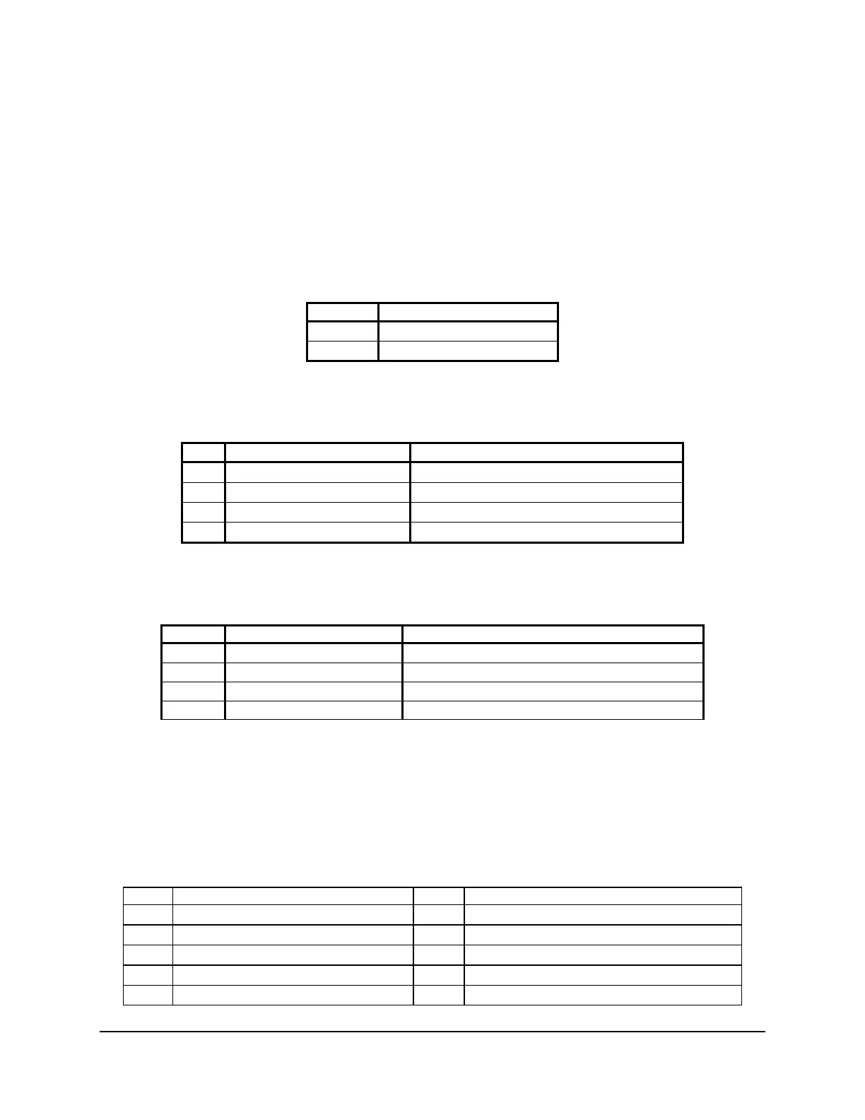
7.2.3 Hard Drive Activity (Input) LED Header
Table 47. SATA HDD Activity (Input) LED Header (J1E3)
Pin Description
1
LED_HD_ACTIVE_L
2 NC
7.2.4 IPMB Header
Table 30. IPMB Header 4-pin (J1B2)
Pin Signal Name Description
1
SMB_IPMB_5VSB_DAT
BMC IPMB 5V standby data line
2
GND
Ground
3
SMB_IPMB_5VSB_CLK
BMC IPMB 5V standby clock line
4
P5V_STBY
+5V standby power
7.2.5 SGPIO Header
Table 31. SGPIO Header (J1B1)
Pin Signal Name Description
1
SCLOCK
SGPIO Clock Signal
2
SLOAD
SGPIO Load Signal
3
SDOUT0
SGPIO Data Out
4
SDOUT1
SGPIO Data In
7.3 SSI Control Panel Connector
The server board provides a 24-pin SSI front panel connector (J1D3) for use with SSI compliant
third-party chassis. The following table provides the pin-out for this connector.
Table 32. Front Panel SSI Standard 24-pin Connector Pin-out (J1E1)
Pin Signal Name Pin Signal Name
1 P3V3_STBY (Power LED Anode) 2 P3V3_STBY (Front Panel Power)
3 Key 4 P5V_STBY (ID LED Anode)
5 FP_PWR_LED_N 6 FP_ID_LED_BUF_N
7 P3V3 (HDD Activity LED Anode) 8 FP_LED_STATUS_GREEN_N
9 LED_HDD_ACTIVITY_N 10 FP_LED_STATUS_A MBER_N