Functional Architecture Intel® Server Board S5500WB TPS
Revision 1.3
Intel order number E53971-004
26
other channels hold the secondary image of the system memory. The integrated memory
controller in the Intel
®
5500 series alternates between both channels for read transactions.
Under normal circumstances, write transactions are issued to both channels.
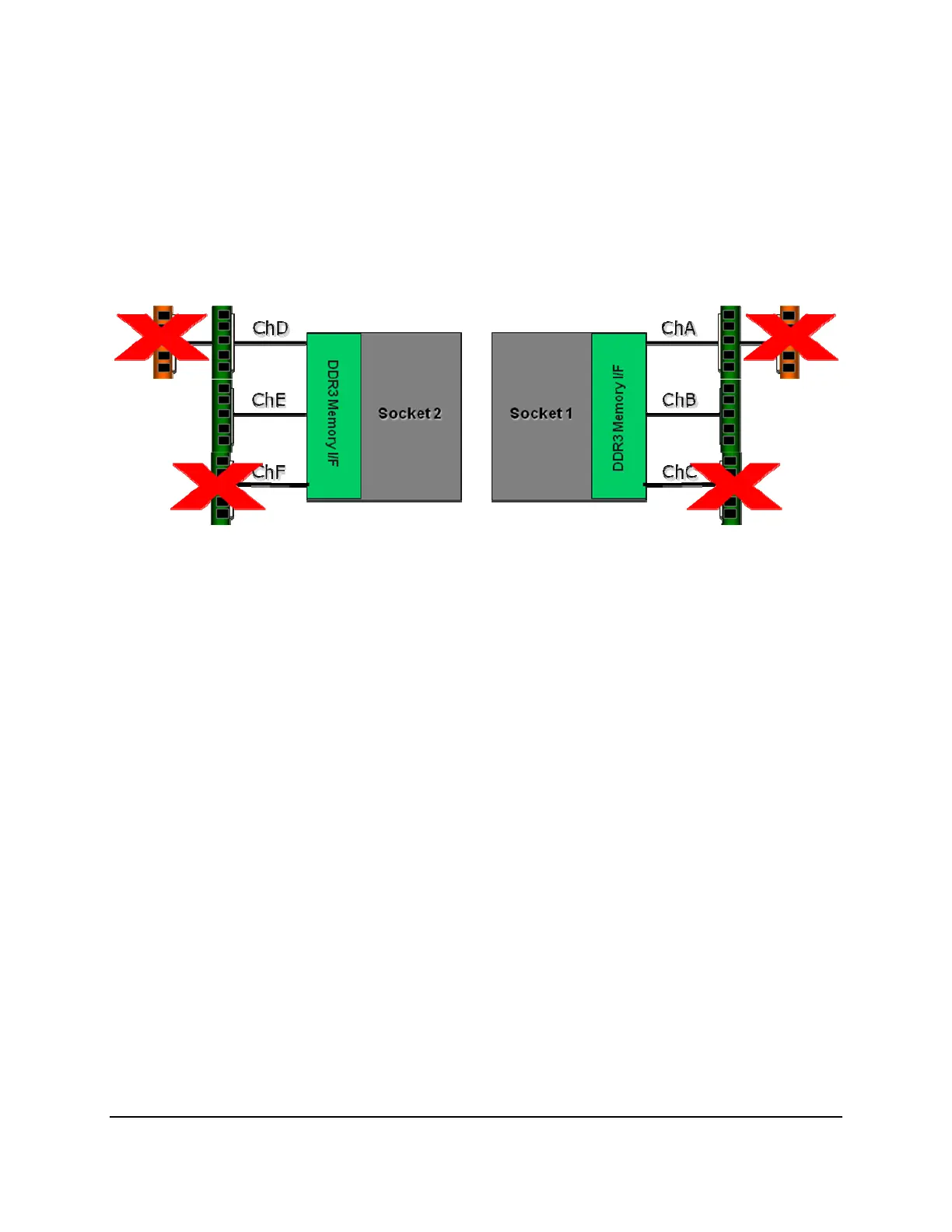
Mirroring is only supported between Channels A & B and Channels D & E. The presence of a
DIMM on Channel C or F causes the BIOS to disable Mirroring and revert to the Independent
Channel mode.
Figure 18. Mirroring Memory Configuration
3.4.10 Memory Error LED
Each DIMM is allocated an LED that, when lit, indicates a memory DIMM failure. It is the
function of the BIOS to identify bad DIMMs during the boot process. The BIOS sends a
message to the BMC to indicate which DIMM LED needs turn on.
3.5 Intel
®
5500 Chipset IOH
The Intel
®
5500 Chipset component is an I/O Hub (IOH). The Intel
®
5500 Chipset provides a
connection point between various I/O components and Intel processors using the Intel
®
QPI
interface.
The Intel
®
5500 Chipset IOH is capable of interfacing with up to 24 PCI Express* lanes, which
can be configured in various combinations of x4, x8, x16 and limited x2 and x1 devices.
The Intel
®
5500 Chipset IOH is responsible for providing a path to the legacy bridge. In addition,
the Intel
®
5500 Chipset supports a x4 DMI (Direct Media Interface) link interface for the legacy
bridge and interfaces with other devices through SMBus, Controller Link, and RMII (Reduced
Media Independent Interface) manageability interfaces. The Intel
®
5500 Chipset supports the
following features and technologies:
• Intel
®
QuickPath Interconnect (Intel
®
QPI)
• PCI Express* Gen2
• Intel
®
Virtualization Technology (Intel
®
VT) for Directed I/O 2 (Intel
®
VT-D2)