Functional Architecture Intel® Server Board S5500WB TPS
Revision 1.3
Intel order number E53971-004
18
Pin 1
C
D
AF003060
.
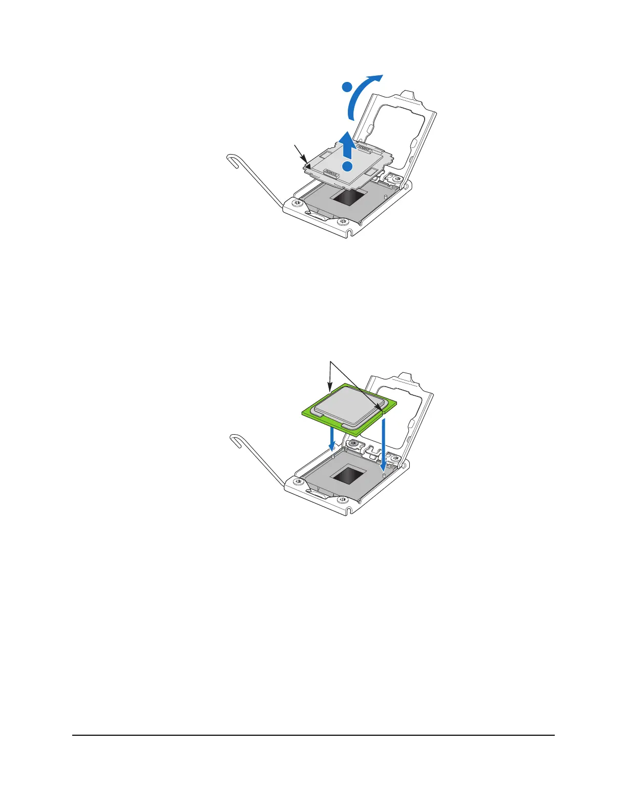
Figure 11. Removing the socket cover
7. Remove the protective socket cover. (See letter “D” in Figure 11)
8. Align the pins of the processor with the socket and insert the processor into the socket.
AF003061
Orientation
Notch
Figure 12. Installing processor
9. Lower the load plate and load lever of the ILM cover completely.
NOTE:
Make sure the alignment triangle mark and the alignment triangle cutout align
correctly. To assist in package orientation and alignment with the socket:
A. The package Pin1 triangle and the socket Pin1 chamfer provide a visual reference for
proper orientation.
B. The package substrate has orientation notches along two opposing edges of the
package offset from the centerline. The socket has two corresponding orientation