Functional Architecture Intel® Server Board S5500WB TPS
Revision 1.3
Intel order number E53971-004
24
3.4.7 Installing and Removing Memory
The silkscreen on the board next to CPU1 displays: DIMM_A2, DIMM_A1, DIMM_B1,
DIMM_C1, and next to CPU2 display: DIMM_D2, DIMM_D1, DIMM_E1, DIMM_F1 starting from
the inside of the board. DIMM_A1 is the blue socket closest to the CPU 1 socket. For memory
channel A, the server board requires DDR3 DIMMs within a channel to be populated starting
with the DIMM farthest from the processor. The DIMM farthest from the processor per channel
is blue on the board.
3.4.7.1 Installing DIMMs
To install DIMMs, follow these steps:
1. Turn off the server.
2. Disconnect the AC power cord from the server.
3. Remove the server’s cover and locate the DIMM sockets (see “Installing Memory”).
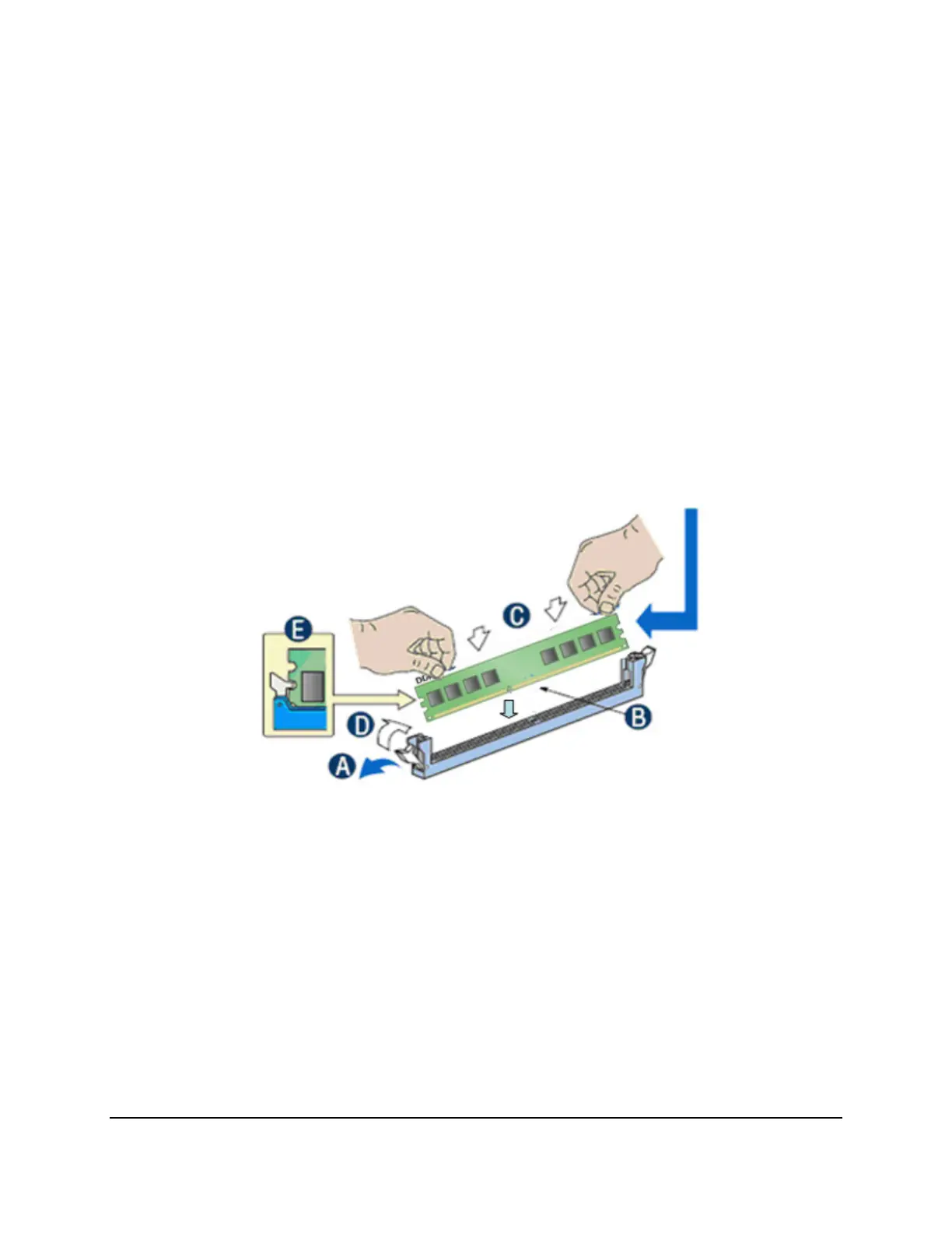
Figure 17. Installing Memory
4. Make sure the clips at either end of the DIMM socket(s) are pushed outward to the open
position (see letter “A” in the figure above).
5. Holding the DIMM by the edges, remove it from its anti-static package.
6. Position the DIMM above the socket. Align the two small notches in the bottom edge of
the DIMM with the keys in the socket (letter “B” in Figure 16).
7. Insert the bottom edge of the DIMM into the socket (letter “C” in Figure 16).
8. When the DIMM is inserted, push down on the top edge of the DIMM until the retaining
clips snap into place (letter “D” in Figure 16). Make sure the clips are firmly in place
(letter “E” in Figure 16).
9. Replace the server’s cover and reconnect the AC power cord.