Intel® Server Board S5500WB TPS Design and Environmental Specifications
Revision 1.3
Intel order number E53971-004
77
Table 53. Fan Connector Location & Detail
CPU 2 Memory 2
FAN_CPU2 FAN_CPU2A FAN_MEM2 FAN_MEM2R
PWM_CPU0 PWM_CPU0 PWM_MEM0 PWM_MEM0
Tach 3 Tach 7 Tach 4 Tach 4 & 8
J3E1 J2J2 J2J1 J1D5
LED_Fan_Fault_CPU0 LED_Fan_Fault_CPU0A LED_Fan_Fault_MEM0 LED_Fan_Fault_MEM0R
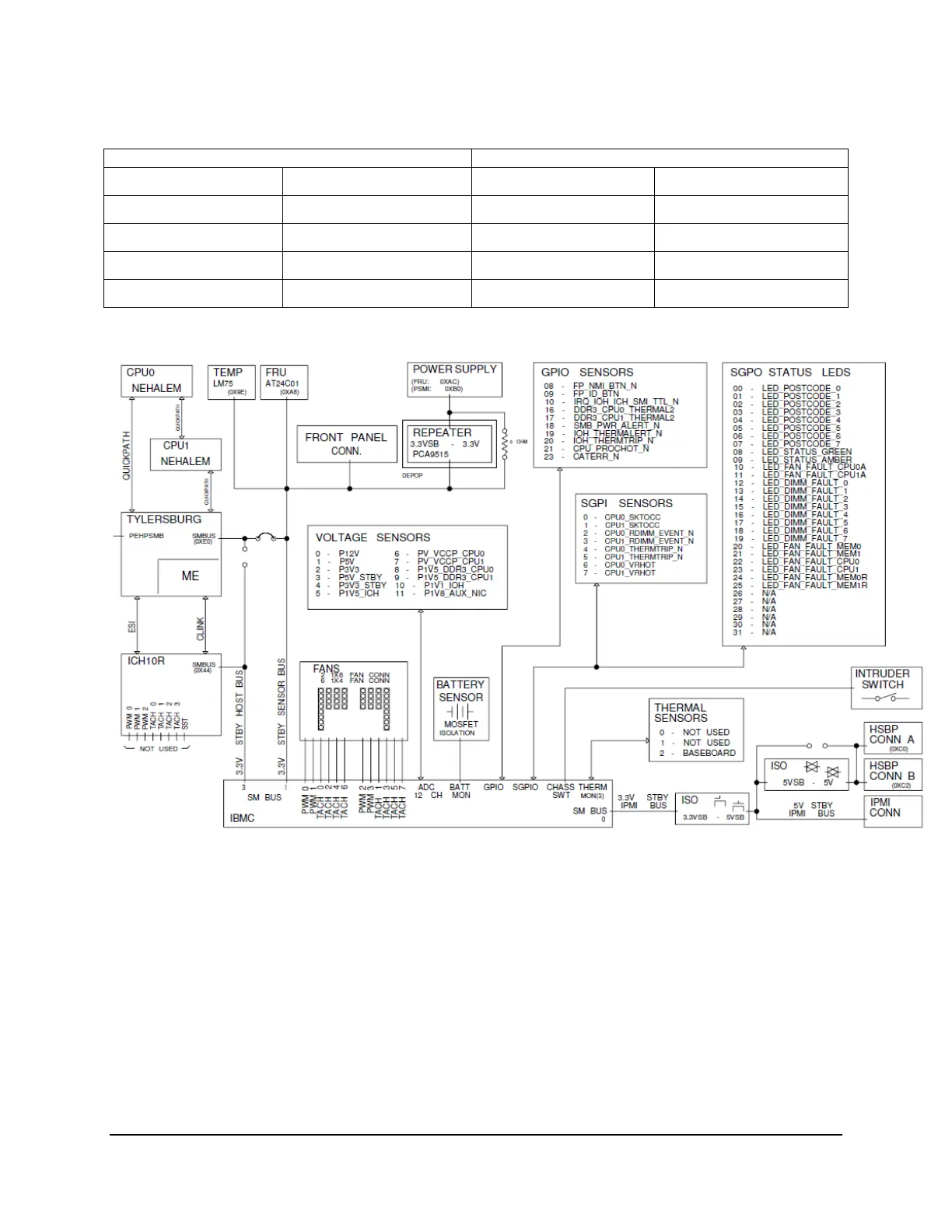
Figure 29. Fans and Sensors Block Diagram
9.2 Thermal Sensors
9.2.1 Processor PECI Temperature Sensor
The processor thermal control uses a CPU PECI thermal sensor, which is a relative temperature
off PROCHOT# trip point (a -20C reading means 20C below PROCHOT# trip point
temperature). The BMC can get the Intel
®
5500 series processor PECI Tcontrol values for each
CPU installed to use/follow the clamped algorithm for component thermal sensor. The following
sample SDR settings could be used:
• Use Tcontrol (byte 8, bit 0 = 1): Tcontrol value is provided by BIOS via the Set CPU
TControl command for the indicated CPU is used.