Intel® Server Board S5500WB TPS Connector / Header Locations and Pin-out
Revision 1.3
Intel order number E53971-004
61
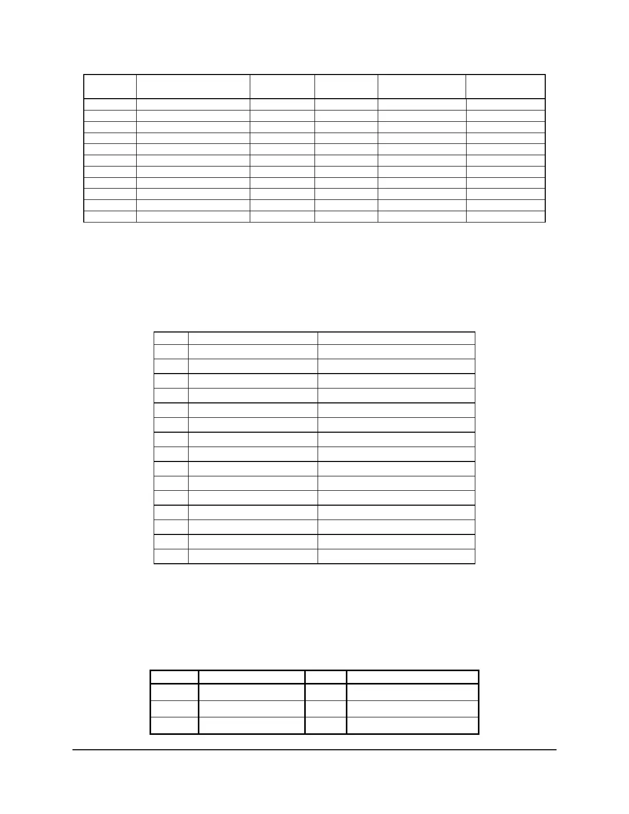
Pin-Side B PCI Express* Spec Signal Description Pin-Side A PCI Express* Spec
Signal
Description
39 GND 39
40 GND 40
41 41 GND
42 42 GND
43 GND 43
44 GND 44
45 45 GND
46 46 GND
47 GND 47
48 PRSNT2# 48
49 GND 8X end 49 GND
7.4.2 VGA Connectors
The following table details the pin-out definition of the external VGA connector (J6A1).
Table 38. VGA External Video Connector (J6A1)
Pin Signal Name Description
1 V_IO_R_CONN Red (analog color signal R)
2 V_IO_G_CONN Green (analog color signal G)
3 V_IO_B_CONN Blue (analog color signal B)
4 TP_VID_CONN_B4 No connection
5 GND Ground
6 GND Ground
7 GND Ground
8 GND Ground
9 TP_VID_CONN_B9 No connection
10 GND Ground
11 TP_VID_CONN_B11 No connection
12 V_IO_DDCDAT DDCDAT
13 V_IO_HSYNC_CONN HSYNC (horizontal sync)
14 V_IO_VSYNC_CONN VSYNC (vertical sync)
15 V_IO_DDCCLK DDCCLK
The following table details the pin-out definition of the internal VGA connector (J1D1).
Table 39. VGA Internal Video Connector (J1D1)
Pin Signal Name Pin Signal Name
1
Red
2
R_RTN(Red Return)
3
Green
4
G_RTN(Green Return)
5
Blue
6
B_RTN(Blue Return)