Connector / Header Locations and Pin-out Intel® Server Board S5500WB TPS
Revision 1.3
Intel order number E53971-004
66
One low-profile 2x5 connectors (J1D4) on the server board provides an option to support low-
profile USB based embedded flash devices. The pin-out of the connector is detailed in the
following table.
Table 47. Low-Profile Internal USB Connector (J1E2)
Pin Signal Name Pin Signal Name
1 +5V 2 NC
3 USB_N 4 NC
5 USB_P 6 NC
7 GND 8 NC
9 Key Pin 10 LED#
7.5 Fan Headers
The server board provides six SSI-compliant 4-pin fan headers and two 8-pin fan headers to be
used for CPU, and IO cooling. The pin configuration for each of the 4-pin fan headers is
identical and defined in the following tables.
Table 48. SSI 4-pin Fan Connector (J2K2, J2K3, J3K1, J7K1, J8K4, J8K5)
Pin Signal Name Description
1
GND
Ground
2
12V
Power Supply 12V
3
TACH IN
FAN_TACH signal is connected to the BMC to monitor the fan speed
4
PWM OUT
FAN_PWM signal to control fan speed
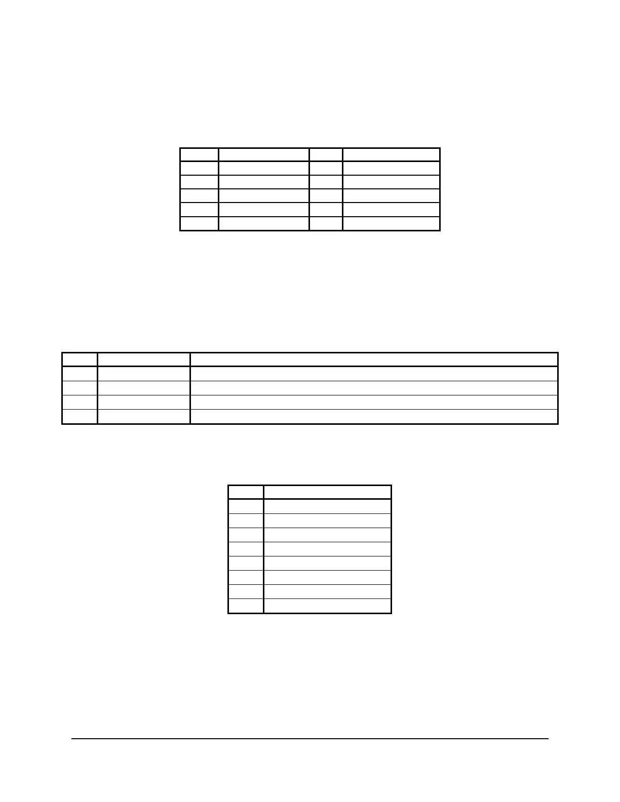
Table 49. 8-pin Fan Connector (J2K1 & J8K3)
(MOLEX CONNECTOR CORPORATION 53398-0890 or 53398-0871 )
Pin Signal Name
1
GND
2
12V
3
Tach0
4
PWM0
5
GND
6
12V
7
Tach1
8
PWM1