Connector / Header Locations and Pin-out Intel® Server Board S5500WB TPS
Revision 1.3
Intel order number E53971-004
58
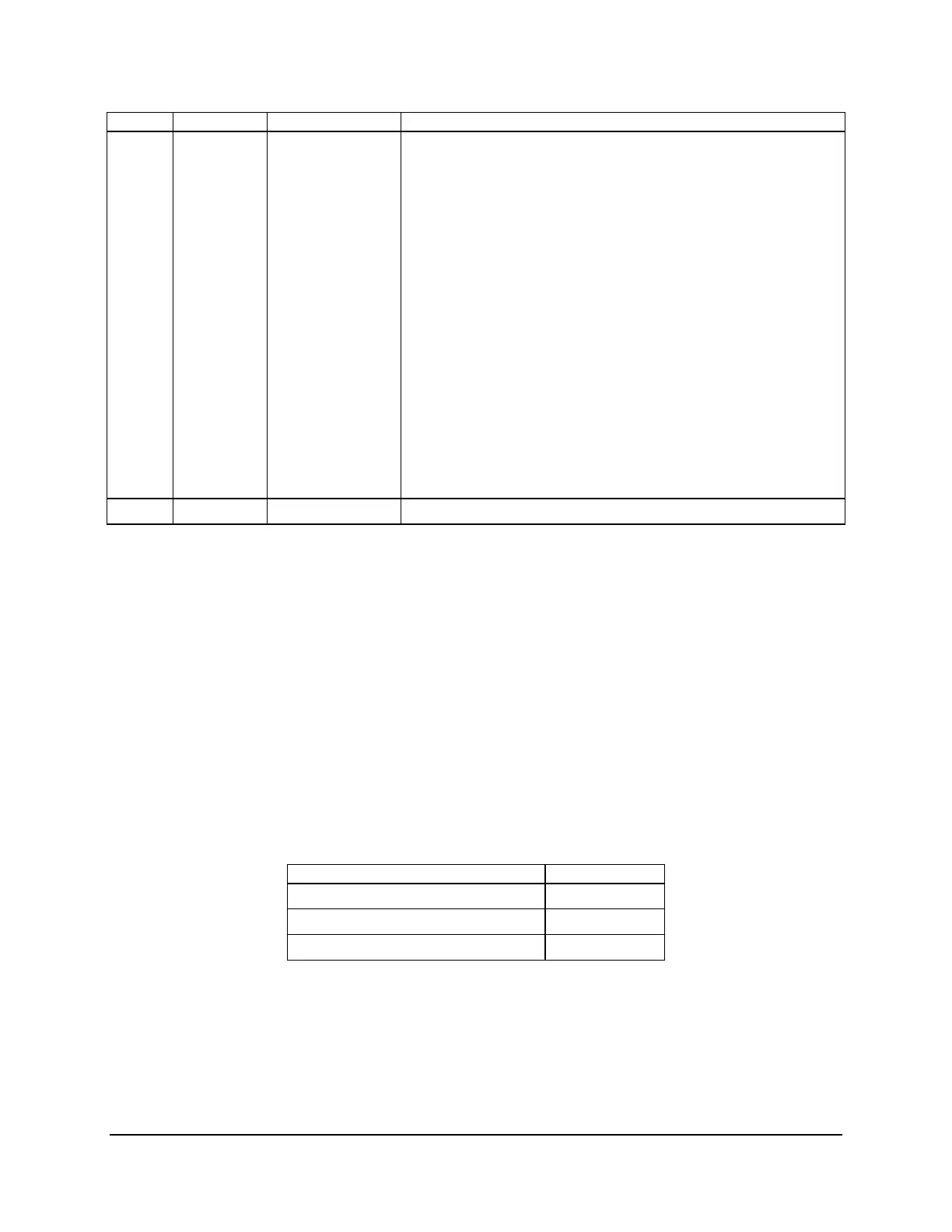
Color State System Status Description
Amber Solid on Fatal Fatal alarm – system has failed or shut down:
BIOS Detected
1. DIMM failure when there is one DIMM present and
no good memory is present.
1
2. Run-time memory uncorrectable error in non-
redundant mode.
1
3. CPU configuration error (for instance, processor
stepping mismatch).
Integrated BMC Detected
1. CPU CATERR signal asserted.
2. CPU 1 is missing.
3. CPU THERMTRIP.
4. No power good – power fault.
5. Power Unit Redundancy sensor – Insufficient
resources offset (indicates not enough power
supplies are present).
Off N/A Not ready Main power off
Notes:
1. The BIOS detects these conditions and sends a Set Fault Indication command to the
Integrated BMC to provide the contribution to the system status LED.
7.3.7 Chassis ID LED
The chassis ID LED provides a visual indication of a system being serviced. The state of the
chassis ID LED is affected by the following:
Toggled by the chassis ID button
Controlled by the Chassis Identify command (IPMI)
Controlled by the Chassis Identify LED command (OEM)
Table 35. Chassis ID LED Indicator States
State LED State
Identify active via button Solid on
Identify active via command ~1 Hz blink
Off Off
There is no precedence or lock-out mechanism for the control sources. When a new request
arrives, all previous requests are terminated. For example, if the chassis ID LED is blinking and
the chassis ID button is pressed, then the chassis ID LED changes to solid on. If the button is
pressed again with no intervening commands, the chassis ID LED turns off.