Intel® Server Board S5500WB TPS Connector / Header Locations and Pin-out
Revision 1.3
Intel order number E53971-004
63
7.4.4 SATA Connectors
The server board provides up to six SATA / SAS connectors:
• SATA-0 (J9B2)
• SATA-1 (J9B3)
• SATA-2 (J9C1)
• SATA-3 (J9C2)
• SATA-4 (J9B5)
• SATA-5 (J9B4)
The pin configuration for each connector is identical and defined in the following table.
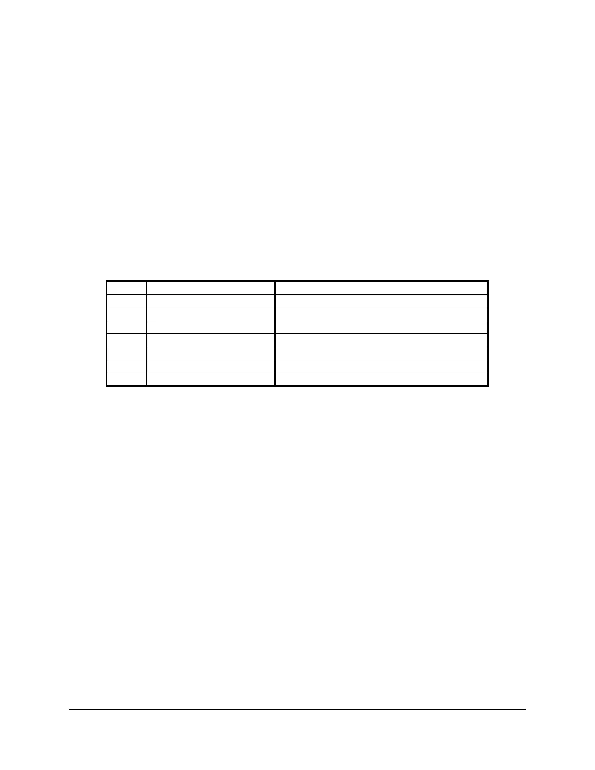
Table 41. SATA Connectors
Pin Signal Name Description
1
GND
Ground
2
SATA_TX_P
Positive side of transmit differential pair
3
SATA_TX_N
Negative side of transmit differential pair
4
GND
Ground
5
SATA_RX_N
Negative side of receive differential pair
6
SATA_RX_P
Positive side of receive differential pair
7
GND
Ground
7.4.5 Intel
®
I/O Expansion Module Connector
The server board provides 2x internal 50-pin Intel
®
I/O Expansion Module style connector
(J2B1, J3B1) to accommodate proprietary form factor Intel
®
I/O Expansion Modules, which
expand the I/O capabilities of the server board without sacrificing an add-in slot from the riser
cards. There are multiple Intel
®
I/O Expansion Modules for use on this server board. For more
information on the supported Intel
®
I/O Expansion Modules, refer to the Intel
®
Server Board IO
Module Hardware Specification. The following table details the pin-out of the Intel
®
I/O
Expansion Module connectors.