SECTION 4—FRONT RIGGINGS
Spree XT 36 Part No 1118364
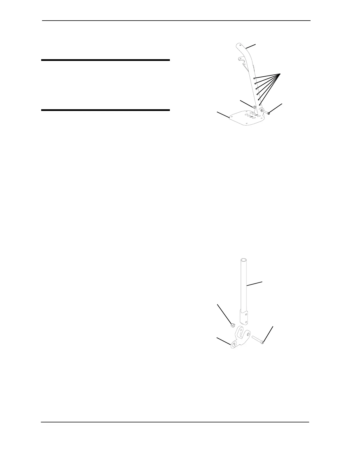
4. Reinstallthesocketboltthroughthe
mountingholesofthefootplateand
footrestsupport.
WARNING
DO NOT overtighten socket bolt and
locknut. Footrest MUST be able to
rotate upward from the horizontal to
the vertical position.
5. Securethefootplatetothefootrest
supportwiththecovedwasherand
locknut.
FIGURE 4.4 Installing/Removing Swingaway
Footrest - 70° MFX, 90°, 70° LIFT and 90°
LIFT Footrests
Installing Adjustable Angle Flip-Up Footplate Hinge
NOTE:Forthisprocedure,refertoFIGURE4.5.
1. Positiontheadjustableangleflip‐upfootplatehingeonthefootrestsupporttubeatthe
desiredheight.
2. PositionthehardwareonthefootrestsupportasshowninFIGURE4.4.
3. Flipthefootplatehingetotheupposition.
NOTE:Thefootplatehingewillfalltothedownposition.
4. Tightenthesocketscrewandlocknut
thatsecurethefootplatehingetothe
footrestsupportuntilthefootplate
hingeremainsintheupposition.
5. Checktheupanddownmotionofthe
footplatehingetomakesuretheuserof
thewheelchaircanoperatethe
footplateseasily.
NOTE:Ifthe
footplateʹsmotionistootight,
loosenthesocketscrewandlocknut
approximately¼‐turn.
NOTE:Ifthefootplateʹsmotionistooloose,
tightenthesocketscrewandlocknut
approximately¼‐turn.
FIGURE 4.5 Installing Adjustable Angle
Flip-Up Footplate Hinge
Height
Adjustment
Holes
Socket Bolt
Locknut
Footrest Support
Footplate
Footrest
Support
Tube
Socket Screw
Locknut
Footplate
Hinge