IPE300 series engineering VFD Function parameter list
-133-
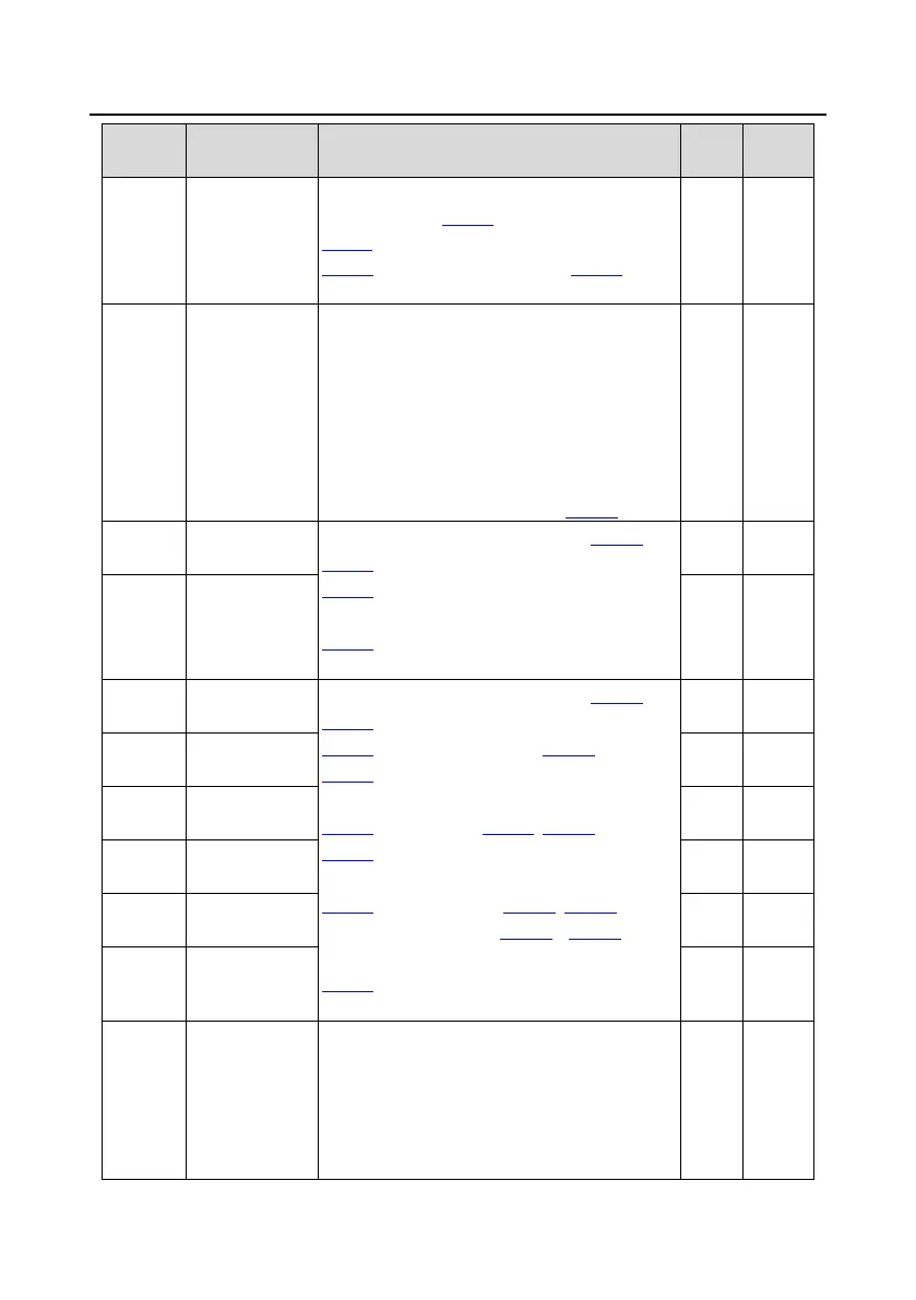
Oscillation
control threshold
of motor 1
phenomenon.
Setting range of P04.10: 0–100
P04.11 setting range: 0–100
P04.12 setting range: 0.00Hz–P00.03 (Max.
output frequency)
V/F curve setting
of motor 2
This group of function code defines the V/F curve
of motor 2 to meet the needs of different loads.
0: Straight-line V/F curve
1: Multi-point V/F curve
2: Torque-down V/F curve (power of 1.3)
3: Torque-down V/F curve (power of 1.7)
4: Torque-down V/F curve (power of 2.0)
5: Customized V/F curve (V/F separation)
Note: Refer to the description for P04.00.
Note: Refer to the descriptions for P04.01 and
P04.02.
P04.14 setting range: 0.0%: Automatic,
0.1%–10.0%
P04.15 setting range: 0.0%–50.0% (of the rated
frequency of motor 2)
Torque boost
cut-off of motor 2
V/F frequency
point 1 of motor 2
Note: Refer to the descriptions for P04.03 and
P04.08.
P04.16 setting range: 0.00Hz–P04.18
P04.17 setting range: 0.0%–110.0% (of the rated
voltage of motor 2)
P04.18 setting range: P04.16–P04.20
P04.19 setting range: 0.0%–110.0% (of the rated
voltage of motor 2)
P04.20 setting range: P04.18–P12.02 (Rated
frequency of AM 2) or P04.18– P12.16 (Rated
frequency of SM 2)
P04.21 setting range: 0.0%–110.0% (of the rated
voltage of motor 2)
V/F voltage point
1 of motor 2
V/F frequency
point 2 of motor 2
V/F voltage point
2 of motor 2
V/F frequency
point 3 of motor 2
V/F voltage point
3 of motor 2
V/F slip
compensation
gain of motor 2
Used to compensate for the motor rotating speed
change caused by load change in the space
voltage vector mode, and thus improve the
rigidity of the mechanical characteristics of the
motor. You need to calculate the rated slip
frequency of the motor as follows:

 Loading...


