IPE300 series engineering VFD Function parameter list
-132-
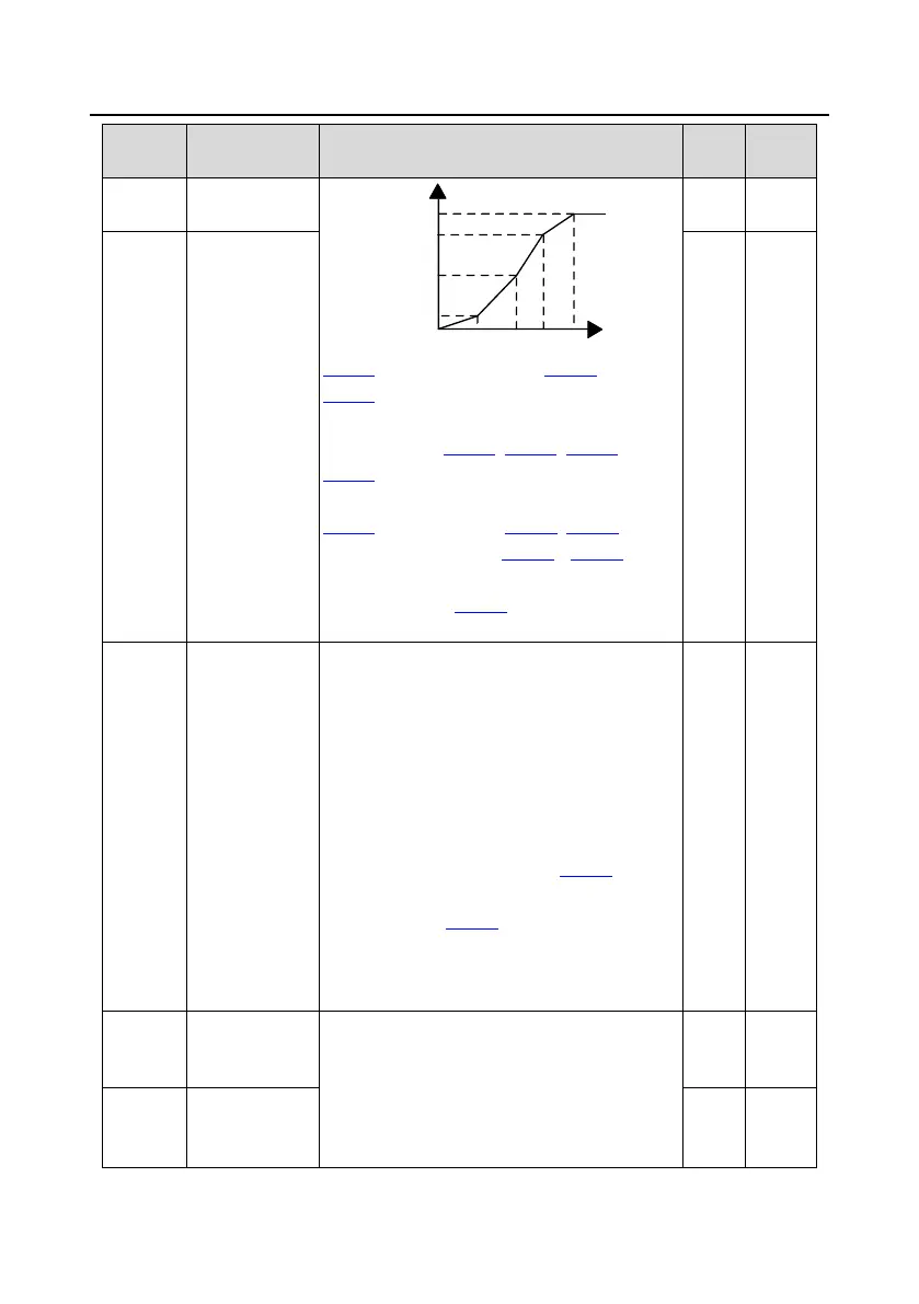
V/F frequency
point 3 of motor 1
Output voltage
Output
frequency(Hz)
V1
V2
V3
f1 f2 f3
100.0%
b
f
b
V
P04.03 setting range: 0.00Hz–P04.05
P04.04 setting range: 0.0%–110.0% (of the rated
voltage of motor 1)
Setting range of P04.05: P04.03–P04.07
P04.06 setting range: 0.0%–110.0% (of the rated
voltage of motor 1)
P04.07 setting range: P04.05–P02.02 (Rated
frequency of AM 1) or P04.05– P02.16 (Rated
frequency of SM 1)
Setting range of P04.08: 0.0%–110.0% (of the
rated voltage of motor 1)
V/F voltage point
3 of motor 1
V/F slip
compensation
gain of motor 1
Used to compensate for the motor rotating speed
change caused by load change in the space
voltage vector mode, and thus improve the
rigidity of the mechanical characteristics of the
motor. You need to calculate the rated slip
frequency of the motor as follows:
△f=f
b
-n*p/60
Of which, f
b
is the rated frequency of the motor,
corresponding to function code P02.02. n is the
rated rotating speed of the motor, corresponding
to function code P02.03. p is the number of pole
pairs of the motor. 100.0% corresponds to the
rated slip frequency △f of motor 1.
Setting range: 0.0–200.0%
Low-frequency
oscillation control
factor of motor 1
In space voltage vector control mode, the motor,
especially the large-power motor, may
experience current oscillation at certain
frequencies, which may cause unstable motor
running, or even VFD overcurrent. You can adjust
the two function codes properly to eliminate such
High-frequency
oscillation control
factor of motor 1

 Loading...


