EasyManua.ls Logo

INVT IPE300 Series - Page 155

INVT IPE300 Series
383 pages
To Next Page IconTo Next Page
To Previous Page IconTo Previous Page
Loading...
IPE300 series engineering VFD Function parameter list
-144-
Function
code
Name
Description
Default
Modify
P05.17
S3 switch-off
delay
Note: After a virtual terminal is enabled, the state
of the terminal can be changed only in
communication mode. The communication
address is 0x200A.
0.000s
P05.18
S4 switch-on
delay
0.000s
P05.19
S4 switch-off
delay
0.000s
P05.20
HDIA switch-on
delay
0.000s
P05.21
HDIA switch-off
delay
0.000s
P05.22
HDIB switch-on
delay
0.000s
P05.23
HDIB switch-off
delay
0.000s
P05.24
AI1 lower limit
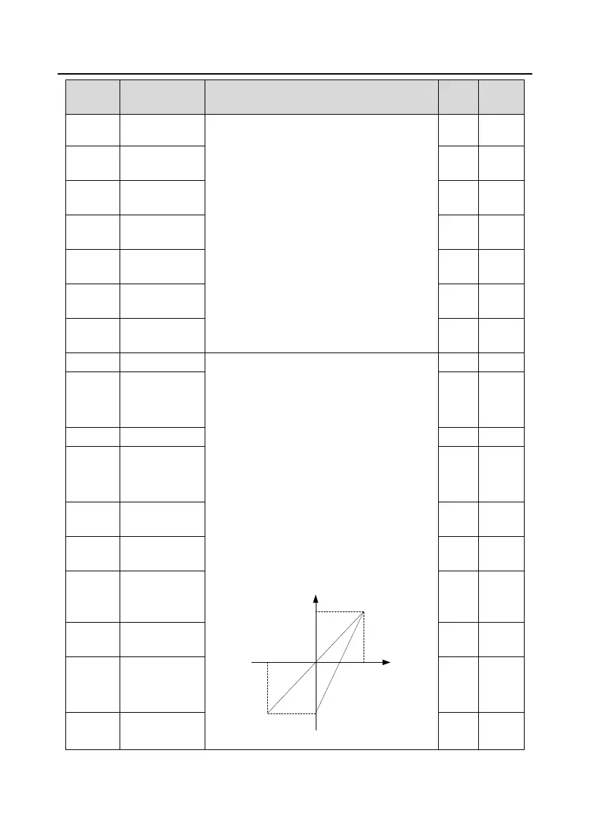
Used to define the relationship between the
analog input voltage and its corresponding
setting. When the analog input voltage exceeds
the range from the upper limit to the lower limit,
the upper limit or lower limit is used.
When the analog input is current input,
0mA20mA current corresponds to 0V10V
voltage.
In different applications, 100.0% of the analog
setting corresponds to different nominal values.
See the descriptions of each application section
for details.
The following figure illustrates the cases of
several settings:
-100%
100%
Corresponding setting
AI
-10V
10V
20mA
0
AI2
AI1
Input filter time: to adjust the sensitivity of analog
0.00V
P05.25
Corresponding
setting of AI1
lower limit
0.0%
P05.26
AI1 upper limit
10.00V
P05.27
Corresponding
setting of AI1
upper limit
100.0%
P05.28
AI1 input filter
time
0.030s
P05.29
AI2 lower limit
-10.00
V
P05.30
Corresponding
setting of AI2
lower limit
-100.0
%
P05.31
AI2 middle value
1
0.00V
P05.32
Corresponding
setting of AI2
middle value 1
0.0%
P05.33
AI2 middle value
2
0.00V

Table of Contents

Related product manuals