/74
R2 CAN Installation manual
4.1.2 Mounting of IRMA MATRIX sensors of the surface mount
version (DIST500-A)
The sensors of the flush mount version (DIST500-A) are placed directly on the door trim and
connected to the sCON-S (standard) from the rear.
Sensors of the surface mount version cannot be mounted together with the connector
version sCON-F-12.
The tools, width across flats and auxiliary tools required for mounting and installation are
shown in section 12.1.2, p. 64.
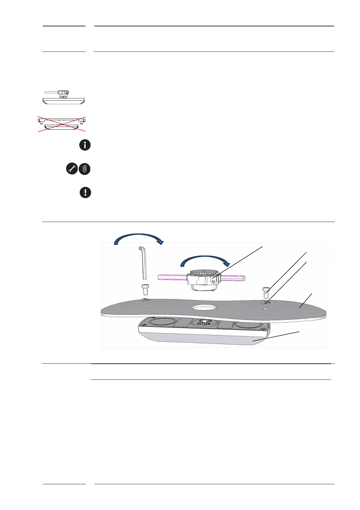
First drill the holes as shown in Fig. 7 with holes of 32 mm and 2 x 6 mm. The drilling
patterns are enclosed in the Annex starting on p. 63.
The sensor is mounted with the mounting screws and pertinent spring washers.
Tighten the screws with a maximum tightening torque of 3 Nm using an Allen key (size 4).
For the mounting of the standard sCON see section 4.1.2.1 on p. 19.
Fig. 7: Mounting of the surface mount version
1 sCON-S (standard)
2,3 Mounting set: 2 screws and 2 spring washers
4 Cove no thicker than 8 mm
5 IRMA MATRIX sensor, surface mount version
1