/74
R2 CAN Installation manual
is available for ordering in the accessories and can then again be used for wall thicknesses
up to 8 mm.
6. For the mounting of the sCON-S (standard) see section 4.1.2.1, p. 19.
If the sensor is installed in color-coated metal coves, it must be ensured that the
connection between sensor housing and cove is conductive.
If the sensor is installed in plastics coves, an additional grounding cable must be installed
between the sensor housing and the chassis (see section 5.3, p. 29).
4.1.3.2 Mounting with sCON-F-12
The sCON-F-12 allows the mounting and electrical connection of the sensor to be
performed simultaneously.
Important mounting properties which result from the selection of the sensor/connector
combination, can be seen in the Annex in section 12.1.2, p. 64.
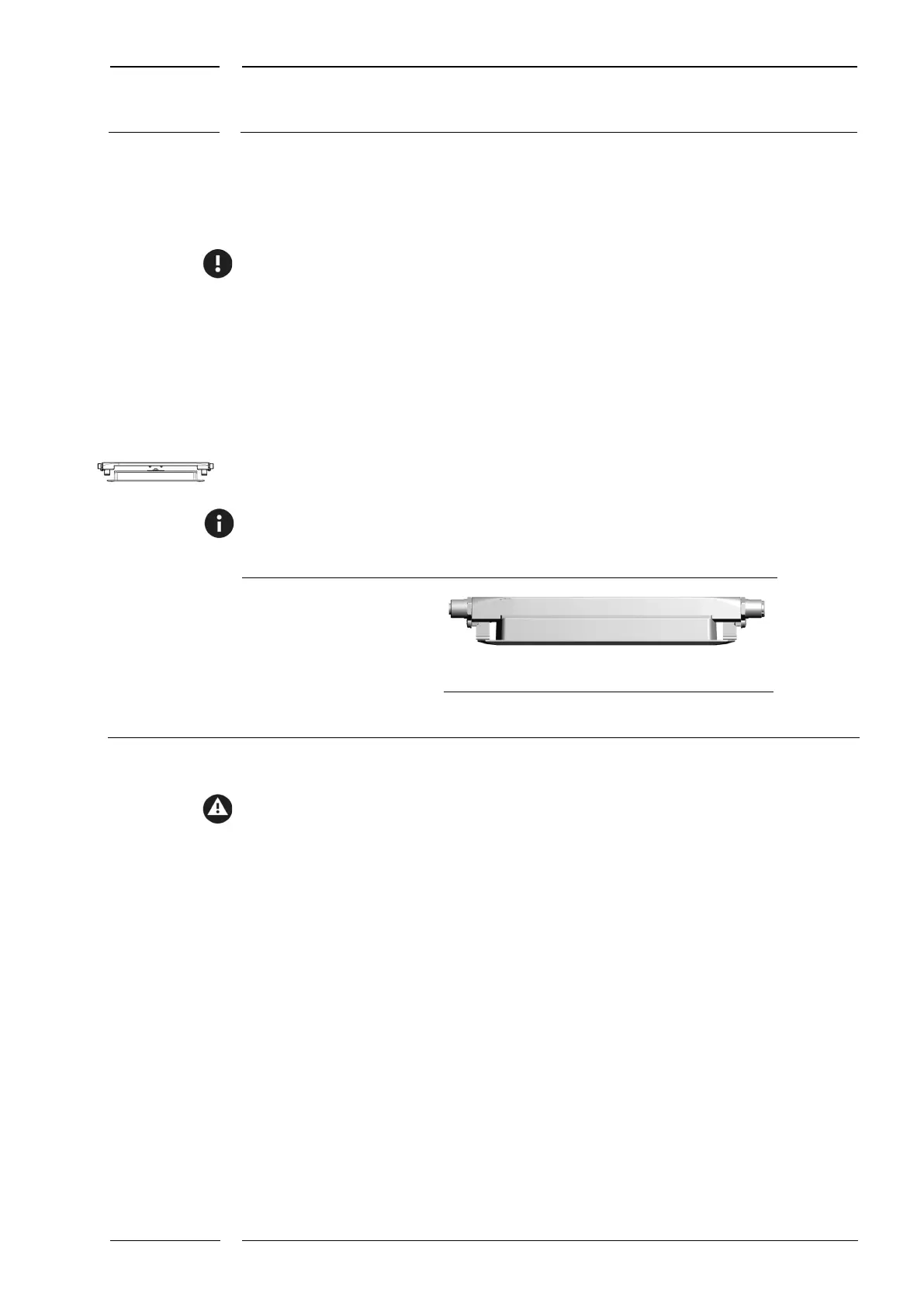
DIST500-F
Fig. 12: Connector version sCON-F-12 w/ Surface mount version sensor
The sCON-F-12 must be de-energized while it is connected to the sensor or disconnected
from it.