/74
MATRIX R2 CAN Installation manual
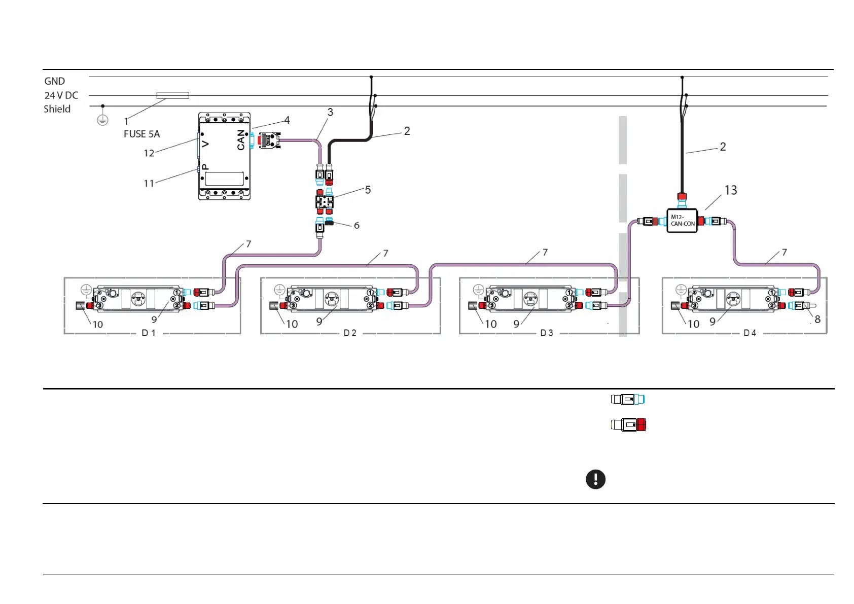
47: Sensor installation in a 4-door vehicle with sCON-F-12 - IRMA gateway in the center (M12 connector)
Fuse 5 A, quick-acting
Power cable with M12 cnnector (f), type CAN/
2 wires and shield
K-M12POW-B-04-2m or K-M12POW-B-oE-04-2m;
or
Connecting cable, CAN type with M12 connector (f), type CAN/
4 wires and shield; K-M12CAN-B-01-1m
SUB-D9 M12 adapter, CAN type
without terminator, without power supply
K-A21-M12CAN-oP-01-32cm
IRMA gateway: IRMA-Gateway-x-XXXX
M12 H coupler of the CAN type, M12CAN-CON-03
M12 extension cable, CAN type; K-M12CAN-XX-x
M12 termination connector (m) of the CAN type;
M12CAN-TR-02
sCON-12 with MATRIX sensor DIST500-F (flush mount variant)
M12 protective cap
Power supply connection (P) e.g.: K-A21-P-01-15m
11 OBC/door contact connection (V) e.g.: K-A21-V-IBIS-07-15-15-15-15-15m
M12 connector (male), CAN type
M12 connector (female), CANtype
-CAN-CON
- D4 Doors with one sensor
Attention: the voltage suppl
y via CAN (13) is made after an
or after 4 IRMA MATRIX sensors.