/74
R2 CAN Installation manual
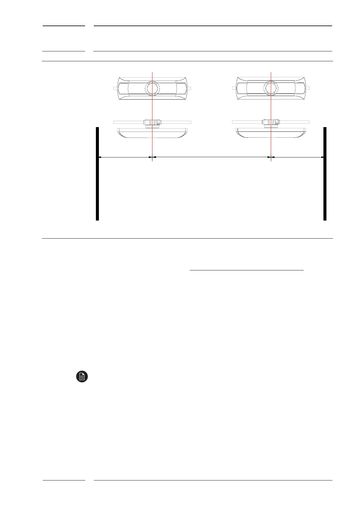
Fig. 18: 2 IRMA MATRIX sensors per door (X = sensor distance)
Deviations from the specification Y1 = Y2 are permissible in accordance with the following
formula:
=
ℎ − ℎ
2
The maximum door width with one sensor is taken from Fig. 15 (blue line). For X, no
deviation is permissible.
5 Laying and connection of the cables
5.1 Available cable characteristics: K01-K05 (formerly K2, K3)
See data sheet "KDDB_IRMA-MATRIX_R2_Data-Sheet_2.0_en" for the cable characteristics
K01 to K05. The former cable characteristics K2 and K3 are broken down here.
5.2 Installations in accordance with EN 50343 (railway
vehicles)
For installations in accordance with EN 50343 (for railway vehicles) cables of the iris cable
characteristic "K3" must be used (see section 5.1). This cable is additionally shielded, which
yields sufficient electrical isolation.