/74
R2 CAN Installation manual
8.1.2.1 PC connection with sCON-S (standard) of the type
sCON-S-CAN-ETH-23-K2-x-y
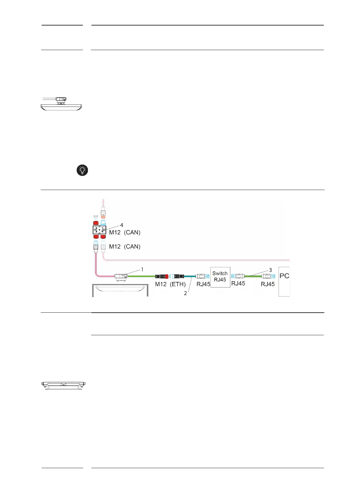
The sCON-S of the sCON-S-CAN-ETH-23-K2-x-y type with its interfaces for CAN and
Ethernet and the cables required for connection can be seen from section 12.2, p. 65, as
CAN component. It is equipped with a CAN and an Ethernet interface which are routed
outwards in the form of M12 connectors of the CAN or ETH type.
An adapter cable with RJ45 connector (2) is connected with a switch via the M12 connector
(f) of the ETH type. The connection to the network adapter of the service PC is made with a
commercial patch cable (3), (see Fig. 25).
If the sCON-S-CAN-ETH-23-K2-x-y connector type is firmly mounted during installation,
servicing can be performed quickly and without any further installation being required.
Fig. 25: PC connection via sCON-S (standard) with additional Ethernet interface
1 sCON-S-CAN-ETH-23-K2-x-y
2 M12-RJ45 adapter of the ETH type,
Commercial patch cable
M12-H coupler of the CAN type, M12CAN-CON-03
8.1.2.2 PC connection with sCON-F-12
The interface description for sCON-F-12 and a short description of the available cables are
found in section 12.2, from p. 65 on.
For installation examples with cabling with sCON-F-12 see Fig. 46, p. 71 and Fig. 47, p.72 et
sequ.