/74
R2 CAN Installation manual
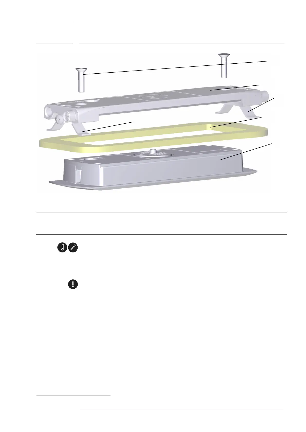
Fig. 13: Mounting with sCON-F-12 – overview
Allen countersunk head screw, Allen key size 3
sCON-F-12
Leaf spring for clamping
Cove
4
(here e.g. 4 mm thick) with rectangular cutout
5 IRMA MATRIX sensor DIST500-F (flush mount variant)
1. Cut the rectangular cutout in the cove 3, see (4) in Fig. 13.
The drilling pattern is enclosed in the Annex to this document.
2. Insert the sensor from below through the rectangular cutout of the cove (3) so that the
plastics window faces the vehicle interior.
Ensure the correct orientation of the sensor; see Fig. 2, p. 11.
• "Exterior" must face outwards when mounted.
• "Interior" must face inwards when mounted.
3. You need to support the sensor with your hand until the connector is screwed tight.
4
A cove is a paneling in the vehicle, here in particular above the door, into which the sensor is to be fitted.