/74
MATRIX R2 CAN Installation manual
1.3 The connector systems
1.3.1 M12 connector of the CAN type
IRMA CAN sensors are connected to the CAN BUS with 5-pole M12 connectors (m/f).
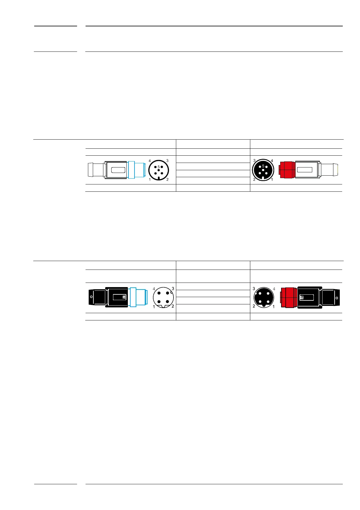
Table 1: Assignment of the CAN type M12 connector (m/f)
M12 connector (m) of the CAN type Pin assignment: M12 connector (f), CAN type
Pole pattern Pin Signal
Pole pattern
Pin 1 Housing and shield
Pin 2 VP+
Pin 3 VP-
Pin 4 CAN-H
5 poles, A coded Pin 5 CAN-L 5 poles, A coded
1.3.2 M12 connector of the ETH type
For service purposes the MATRIX sensor makes an Ethernet interface available. It is connected
with 4-pole M12 connectors of the ETH type.
Table 2: Assignment of the ETH type M12 connector (m/f)
M12 connector (m) of the ETH type Pin assignment: M12 connector (f), ETH type
Pole
pattern
Pin Signal Pole pattern
Pin 1 TD+
Pin 2 RD+
Pin 3 TD-
Pin 4 RD-
4 poles, D coded Housing Shield 4 poles, D coded