/74
IRMA MATRIX R2 CAN Installation manual
released
12.2 Components for IRMA MATRIX Sensors on CAN BUS
Table 14: Overview of the IRMA components on CAN BUS
Connector (f) type Symbol Symbol Connector (m) type
M12 connector (f), CAN type
13
:
M12 connector (m), CAN type
M12 connector (f), ETH type
14
:
M12 connector (m), ETH type
SUB-D9 connector (f), 9 pole
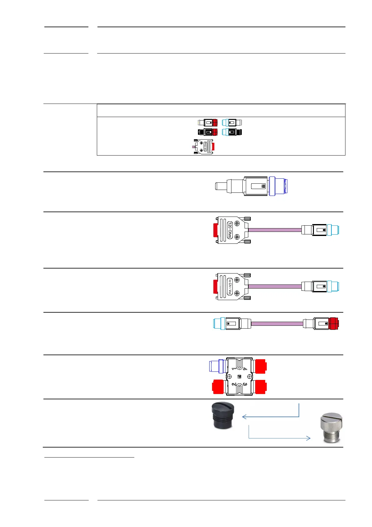
No. Designation Description/function Drawing/product designation
M12 connector
(m) CAN type with
terminator
termination of the CAN BUS with a
resistance of 120 ohms on an H
coupler or at the connection at the
last sensor with sCON-F-12.
M12CAN-TR-02
SUB-D9/M12
with terminator
CAN type adapter cable with
terminator for connection to the
IRMA gateway at the beginning of
the CAN BUS
SUB-D9 connector (f with 120
ohms)/
M12 connector (m), CAN type
K-A21-M12CAN-TRoP-XX-32cm (=K2/K3)
15
3 Adaptor cable
SUB-D9/M12
without
terminator
Adapter, CAN cable
for connection to the IRMA
gateway
SUB-D9 connector (f)/
M12 connector (m), CAN type
K-A21-M12CAN-oP-01-32cm (=K2)
M12 extension cable, CAN type,
connects the coupler and the
sensors
M12 connector (m), CAN type/M12
K-M12CAN-XX-xm (=K2/K3)
M12 connector,
CAN type
The H coupler ensures branchings
(branch lines) of up to 2 CAN BUS
devices per coupler.
M12 connector (m), CAN Type -->
3 x M12 connector (f), CAN Type
M12CAN-CON-03
plastics
or metal
For closing unused M12 connectors
of M12 H couplers
13
For the definition of CAN type connectors see section 1.3.1
14
For the definition of ETH type connectors see section 1.3.2, page 9.
15
-K2-/-K3: for meaning see section 5.1.
-CON-04