/74
MATRIX R2 CAN Installation manual
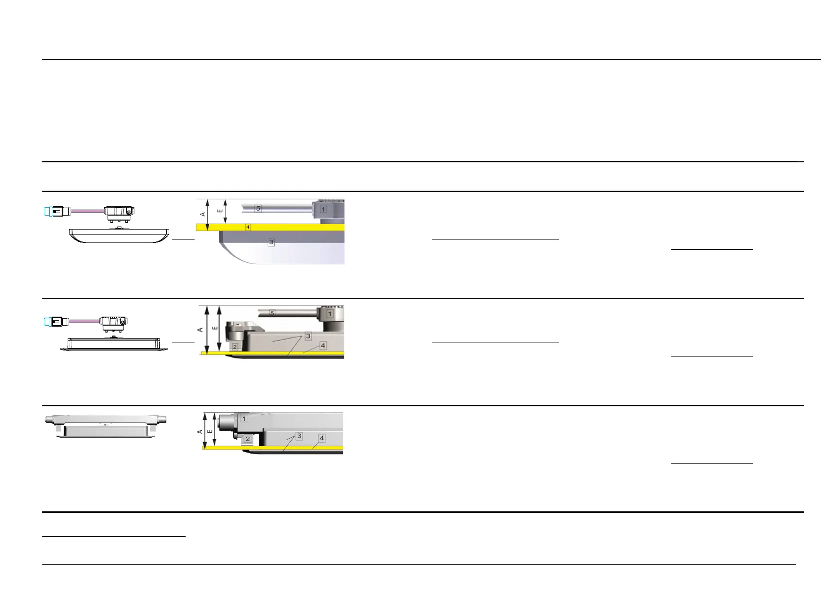
12.1.2 Installation conditions for IRMA MATRIX sensors with different sensor/connector versions
Table 13: Installation conditions for IRMA MATRIX sensors with different sensor/connector versions (required mounting depth, mounting sets and tools)
IRMA MATRIX sensor version
+ sCON version
Required mounting depth
12
= E
E = (A – 8 mm) to (A - 1 mm)
Mounting tools/auxiliary
tools and material
-A; surface mount version +
-S (standard)
1 sCON-S
3 Sensor
4 Cove
5 Connecting cable
A = 21 mm
mm - thickness of cove
Typical mounting depth = 19 mm (13
– 20 mm)
sCON-S-CAN-20-Kn-x
Set_DIST500A-blank-01
Product No.: 0006_87
Torque wrench
with Allen key adapter size 4
Torque wrench M12
For railway installation:
50153 and/or EN 50121-
-2)
spring
washer, yellow/green grounding
cable with line cross section ≥ 1 mm²
sCON-S-CAN-ETH-23-Kn-x-y
-F; flush mount version +
-S (standard)
1 sCON-S
2 Leaf spring
3 Sensor
4 Cove
5 Connecting cable
mm – thickness of cove A = 39 mm
Typical mounting depth = 37 mm (31
– 38 mm)
sCON-S-CAN-20-Kn-x
Set_D500F-01
Product No.: 0006_91
Torque wrench
with Allen key adapter size 4
Torque wrench M12
For railway installation:
to EN 50153 and/or EN 50121-
-2)
spring
yellow/green grounding
cable with line cross section ≥ 1mm²
sCON-S-CAN-ETH-23-Kn-x-y
-F; flush mount version +
-F-12
1 sCON-F-12
2 Leaf spring
3 Sensor
4 Cove
mm – thickness of cove A = 31 mm
Typical mounting depth = 29
mm (23 – 30 mm)
sCON-F-12-CC-E
inclusive
Torque wrench
with Allen key adapter size 3
Torque wrench M12
For railway installation:
50153 and/or EN 50121-
-2)
spring
washer, yellow/green grounding
cable with line cross section ≥ 1 mm²
12
The necessary mounting depth behind the cove (door trim) depends on the thickness of the wall into which the sensor is to be fitted.