/74
R2 CAN Installation manual
4.1.2.1 Mounting of the sCON-S (standard)
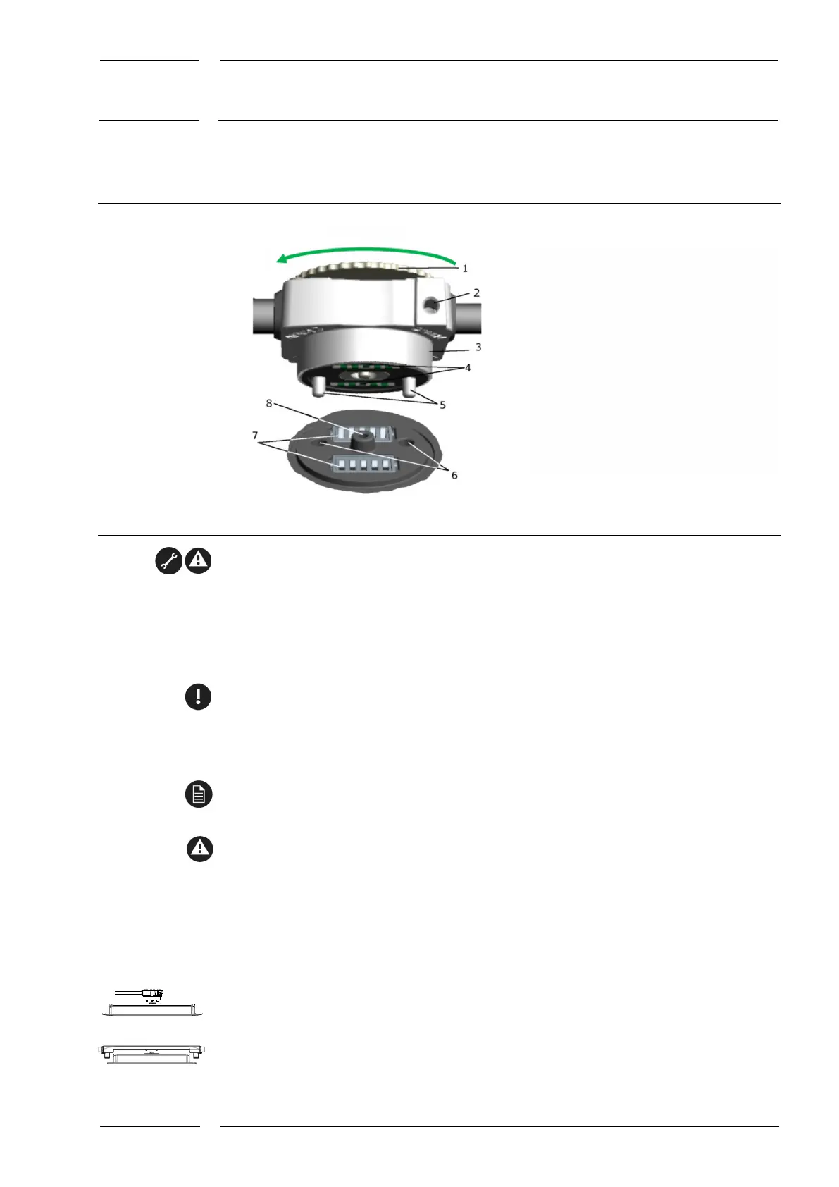
Fig. 8: sCON-S (standard) - overview of the connection components
The connector must be de-energized while it is connected to the sensor or disconnected
from it.
1. Insert the sCON base body with the guiding pins into the guiding holes of the sCON
connection at the sensor until it abuts.
2. Press the sCON base body to the sensor housing and keep it in place. Then tighten the
knurled screw by hand (without a tool) (corresponds to approx. 1 Nm).
If the sensor is installed in color-coated metal coves, it must be ensured that the
connection between sensor housing and cove is conductive.
If the sensor is installed in plastics coves, an additional grounding cable must be installed
between the sensor housing and the chassis (see section 5.3, p. 29).
For the technical data and assignment of the interfaces please refer to the data sheets of
the sCON-S version in question. Please observe the instructions in the data sheet.
The connector must be de-energized while it is connected to the sensor or disconnected
from it.
4.1.3 Mounting of IRMA MATRIX sensors of the flush mount
version (DIST500-F)
The sensors can be mounted either with the sCON-S (standard) and an additional mounting
set, see section 4.1.3.1, p. 20
or with sCON-F-12, see section 4.1.3.2, p. 22.
sCON base body
1 Knurled scew - locks the connection
in place
2 M4 threaded hole for mounting
of ground connection
3 Mounting cylinder for cove depths
of up to 8 mm
4 Contact surfaces
5 Guiding pins
sCON connection on the sensor (rear)
6 Guiding holes
7 Multi-pole connectors on the sensor
8 Threaded mandrel for knurled screw