/74
R2 CAN Installation manual
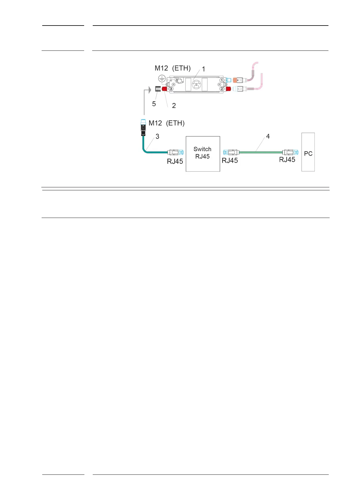
Fig. 26: Service connection to an installation with sCON-F-12
Flat sCON-F-12 with MATRIX sensor DIST500-F (flush mount version)
M12 connector (f), ETH type (connection ) is the Ethernet
connection to the sCON-F-12
3 M12-RJ45 adapter, KQ-M12CAT5-RJ45-01-xm
Commercial patch cable with 2x Rj45 connector (m)
M12 protective cap
To Fig. 26:
The M12 female connector of the ETH type on the sCON-F-12 (item (2) and marking on
the sCON housing) is connected to a switch via an M12-RJ45 adapter (3). The connection
from the switch to the PC is made with a commercial patch cable (4).
In order to be able to configure all sensors in parallel or e.g. for recording test rides, all
sensors must be connected to the switch.