/74
R2 CAN Installation manual
The tools, wrench sizes and mounting sets required for mounting and installation are given
in section 12.1.1, p. 63. The mounting set required for attaching an IRMA MATRIX sensor is
not part of the delivery and must, therefore, be ordered separately.
4.1.3.1 Mounting with sCON-S (standard)
Section 12.1.2, in the Annex on p. 64 gives the tools and mounting accessories required.
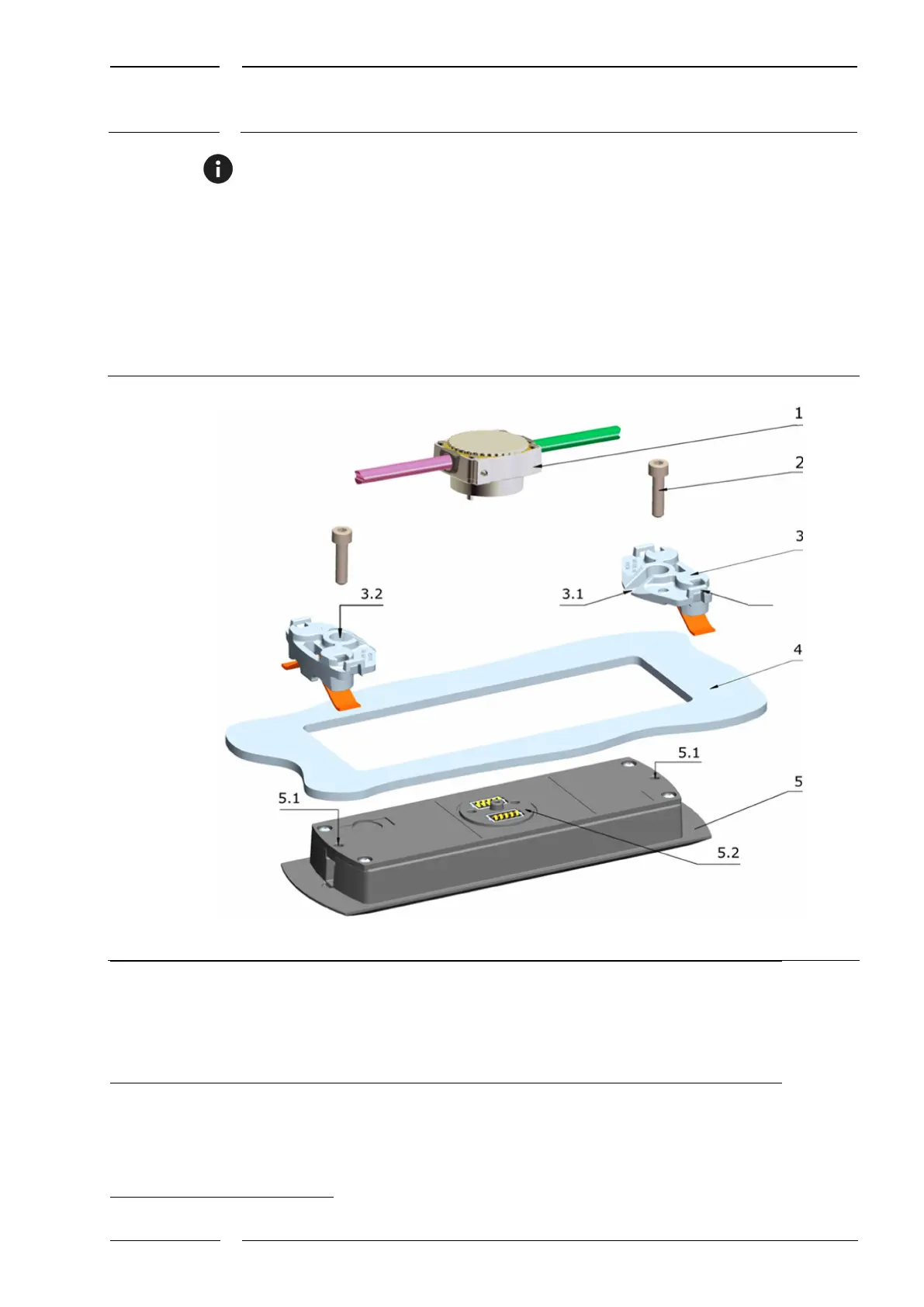
Fig. 9: Mounting with mounting set and sCON-S (standard) - overview
sCON-S (standard)
for IRMA MATRIX sensors
Cylinder head screws (2 pcs.,
mounting set) for
Mounting set comprising 2 spring holders
with pre-mounted leaf spring
Guide groove for sliding
the holding system under the cylinder head screw
3.2
Hole for cylinder head screw for
centering and arresting the sensor
3.3 Fastening eye for cable clip
Cove
3
(here e.g. 4 mm thick)
with rectangular cutout
MATRIX sensor DIST500-F
(flush mount version)
Threaded hole for cylinder head
screw
5.2 sCON connection on the sensor
3
A cove is a paneling in the vehicle interior - here in particular above the door, into which the sensor is to be fitted.