/74
MATRIX R2 CAN Installation manual
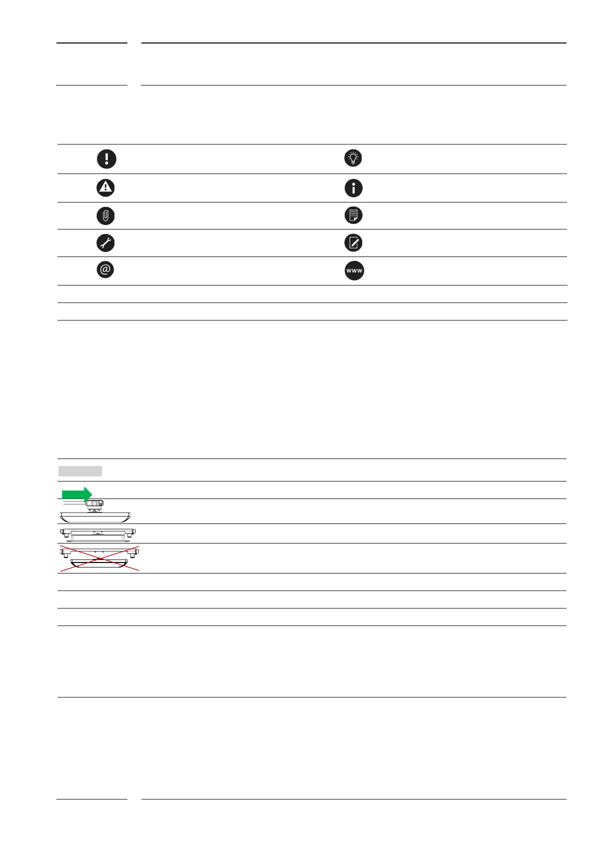
1.2 Symbols/abbreviations/designations used
"Please note!"
"Worth knowing"
"Caution - can result in defects"
"Information"
"See Annex"
"See document on our website"
"Instructions"
"Please note down"
"Please contact iris-GmbH"
"Download"
"Door Polarity"
Setting parameters during configuration are identified as shown on the left.
M12CAN-CON-03
Connector (f)
Female connector
Connector (m)
Male connector
CAN type M12
5-pole M12 connector (m/f) with A coding, see section 1.3.1, p. 9
ETH type M12
4-pole M12 connector (m/f) with D coding, see section 1.3.2, p. 9
Cable type CAN
Cable with 5-pole connectors (m/f), CAN type
Cable type ETH
Cable with 4-pole connectors (m/f), ETH type
Marked grey
Operating instructions for software
This arrow indicates sensor setting parameters which must be adjusted to their environment on each installation.
This section applies to installations with the sCON (standard) connector.
This section applies to installations with sCON-F-12
This section does not apply to installations with MATRIX sensors of the surface mount version.
sCON
Abbreviation of the connector for IRMA MATRIX sensors
sCON-S
Connector (standard) for IRMA MATRIX sensors of the flush mount and surface mount versions
sCON-F-12
Connector for IRMA MATRIX sensors of the flush mount version
x, y
Variable cable lengths or variables in general
-Kn-
Serves as a variable. In the item description it has the following meaning: the product is available in different cable
characteristics. For the description of the cable characteristics K01 – K05 (formerly K2, K3), see section 5.1
-XX-
In the product designation: cable available in different cable characteristics (K2, K3)
VP+/VP-
Power supply of sensor
CAN-H/CAN-L
CAN BUS communication
ETH/ CAN
Ethernet / CAN type interface