/74
MATRIX R2 CAN Installation manual
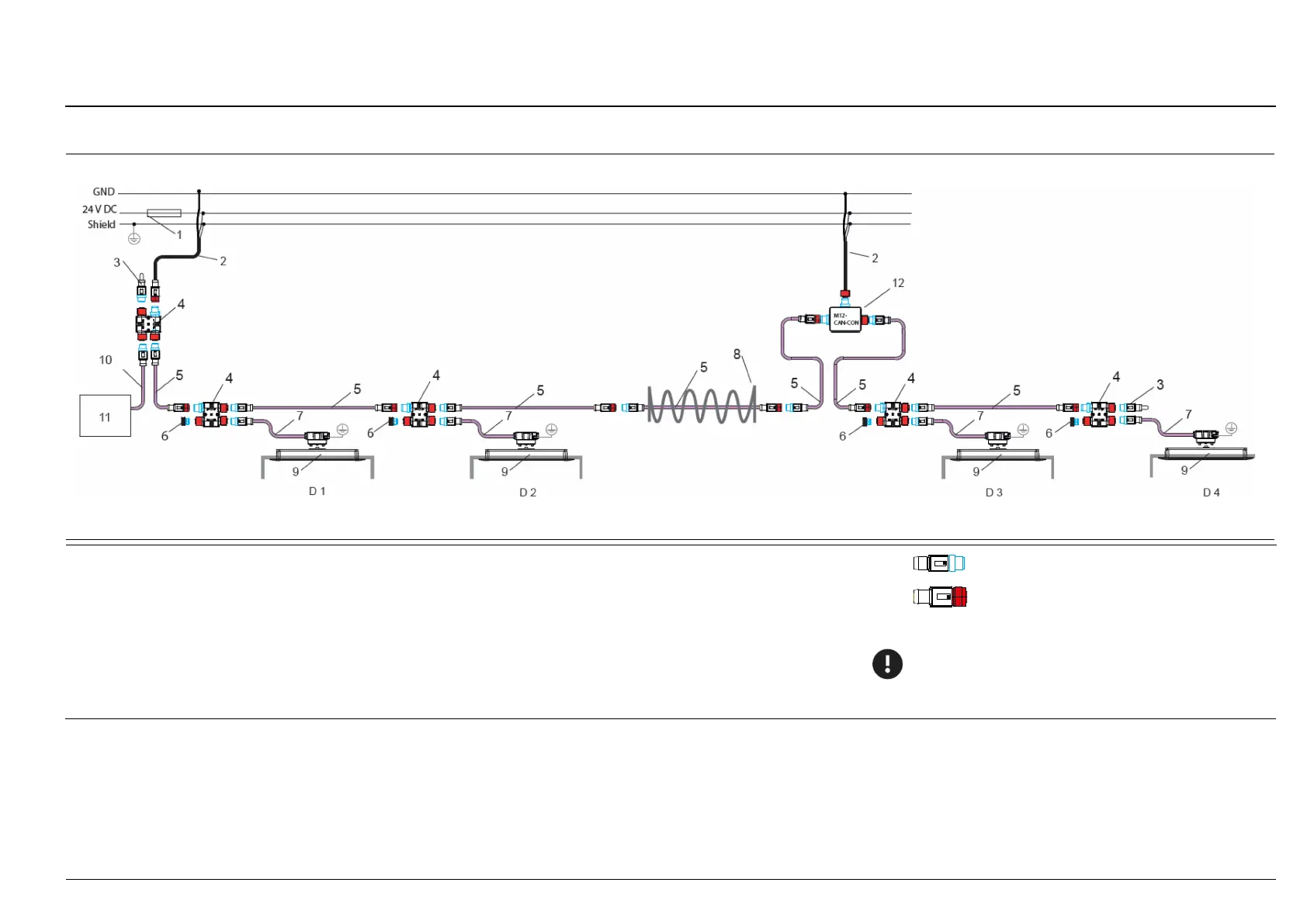
48: CAN installation in a 4-door articulated vehicle (direct connection to the on-board computer, second power supply on the CAN BUS)
Fuse 5 A, quick-acting
Power cable with M12 cnnector (f), type CAN/
2 wires and shield
K-M12POW-B-04-2m or K-M12POW-B-oE-04-2m;
or
Connecting cable, CAN type with M12 connector (f), type CAN/
4 wires and shield; K-M12CAN-B-01-1m
M12 termination connector (m), CAN type; M12CAN-TR-02
M12 H coupler of the CAN type, M12CAN-CON-03
5 M12 extension cable, CAN type; K-M12CAN-XX-x
M12 screw plug; M12CAN-CON-04
sCON-S connector for MATRIX sensor on the CAN BUS; sCON-S-CAN-20-Kn-1m
Articulation
MATRIX sensor DIST500-A (surface mount version) or
DIST500-F (flush mount version)
Connecting cable, CAN type: 4-wires cable with M12 connectors (m)/
4 wires and shield of the opened cable end; K-M12CAN-S-XX-xm
CAN connection of the on-board computer
M12 connector (male), CAN type
M12 connector (female), CAN type
- D4 Doors with one sensor
-CAN-CON
Attention: the voltage suppl
y via CAN (13) is made after an
or after 4 IRMA MATRIX sensors.