/74
R2 CAN Installation manual
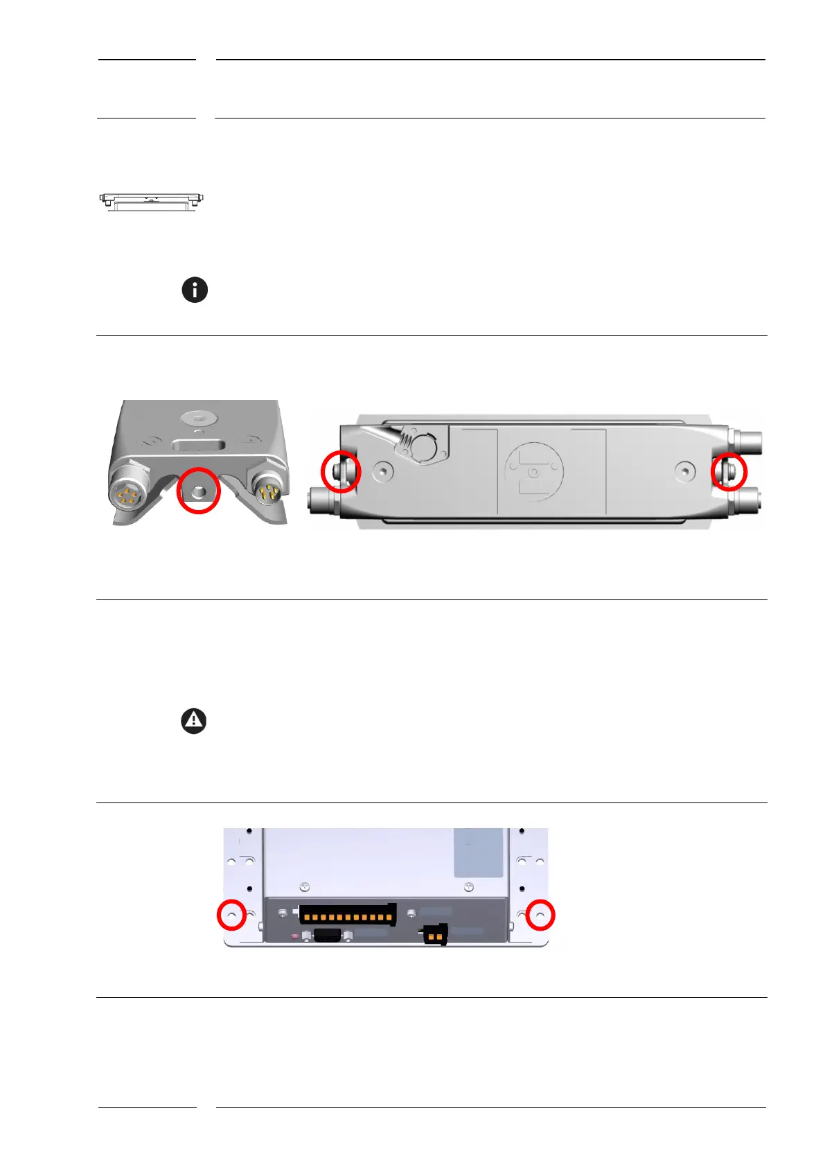
5.3.2 Connection of the grounding cable to the sCON-F-12
Fig. 20 shows the positions on the sCON-F-12 housing provided for connecting the
grounding cable. It attached to a threaded hole in the housing using a crimped eyelet, a
screw (M4x5) and a serrated washer. The other end of the cable is connected to the chassis
potential in a suitable point with a conductive connection.
The connection components required are not part of the standard delivery and must be
provided before the start of mounting.
Fig. 20: sCON-F-12: threaded holes for connecting the grounding cable
5.3.3 Connection of the grounding cable to the IRMA gateway
housing
Fig. 14 shows the positions provided for connecting the grounding cable. The grounding
cable is connected to a mounting hole in the gateway base plate with a low-resistance
connection (see e.g. the markings in Fig. 14). The other end of the cable is connected to the
chassis potential in a suitable point with a conductive connection.
Fig. 21: Mounting holes for attaching the grounding cable