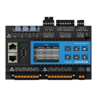
UMG 804 www.janitza.com
24
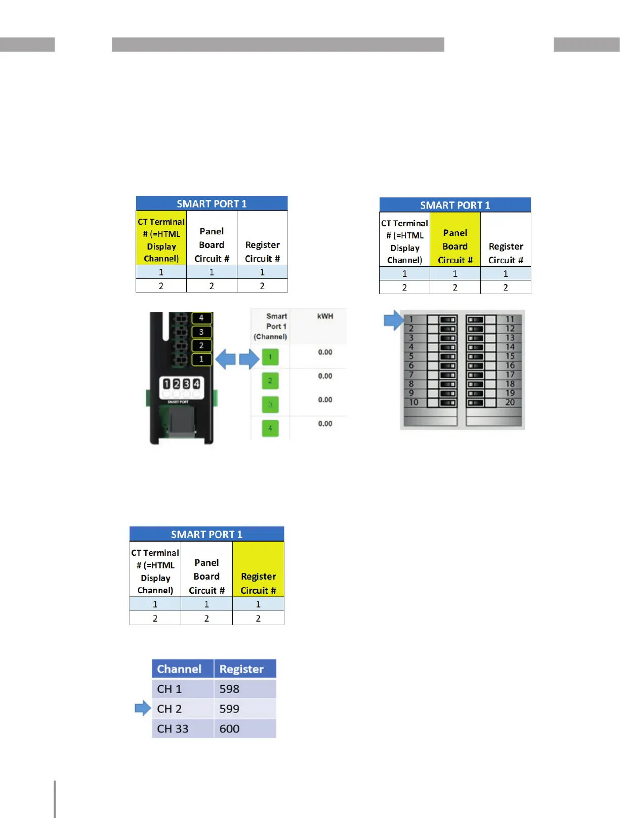
Register Channel:
Indicates the circuit channel on register map
(1-96) that correspods to the related registers.
CT Terminal Number:
Refers to the terminal number on the CT strip
which will also equal the Channel on the HTML
interface.
Panel Board Circuit:
This is the number of the panelboard circuit / pole.
· Orient the DIN Rail CT Interface Floating Boards
according to the panelboard type and numbering
scheme in one of the four configurations shown
in the Interface Board Orientation and Connection
diagrams.
· In Top Feed and Bottom Feed orientations the pa-
nelboard type and numbering is identical however
the user can select to install the Interface Board
with the Smart Port (RJ45 connector) top facing
(Top Feed) or bottom facing (Bottom Feed).
· The UMG 804 must be configured according to
the selected orientation or else channels will not
be aligned the panelboard pole numbers. This is
done during the later in the process.

 Loading...