UMG 804 www.janitza.com
26
4
6
5
2
4
6
8
10
12
14
16
18
20
22
24
26
28
30
32
34
36
38
40
42
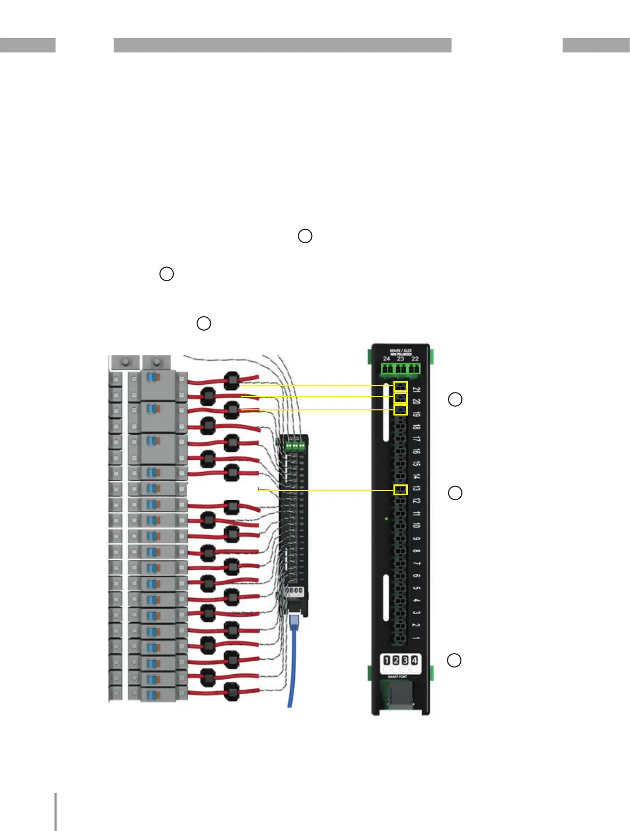
4. Double check that the CTs are connected to
the corresponding conductor. Use the CT Inter-
face Board Orientation and Connection dia-
gram for reference if needed (refer to chapter
„8.2.3 DIN Rail CT Interface Board
Orientation“ on page 38.
5. The number on the position number on the CT
Interface board must correspond to the correct
panel pole number according the Panel Confi-
guration schedule being used, refer to
6. Ensure that unpopulated breakers are skipped,
refer to
7. Ensure that the CT Interface Board is con-
nected to the correct Smart Port on the Core
Module refer to
4
5
6

 Loading...