P/N 960-000180R_Rev. 1 {EDP #233427} © 2016, JAPAN CASH MACHINE CO., LTD.
DBV® Series
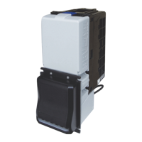
DBV-400 Banknote Validator
List of Tables
Page
Table 1-1 DBV-400 Model Number Specifications .............................................. 1-2
Table 1-2 DBV-400 Type Number Specifications ................................................ 1-2
Table 1-3 DBV-400 Software Number Specifications .......................................... 1-2
Table 1-4 DBV-400 Technical Specifications ...................................................... 1-6
Table 1-5 DBV-400 Environmental Specifications ............................................... 1-7
Table 1-6 DBV-400 Electrical Specifications ....................................................... 1-7
Table 1-7 DBV-400 Structural Specifications ...................................................... 1-7
Table 2-1 DIP Switch Block 1 Settings ................................................................ 2-1
Table 2-2 DIP Switch Block 2 Settings ................................................................ 2-1
Table 2-3 Bezel LED Color DIP SW2 Settings .................................................... 2-2
Table 2-4 DBV-400 ID-003 MDB/Photo-Coupler Isolation Connector
Pin Assignments .................................................................................. 2-3
Table 2-5 DBV-400 ID-003 RS232 Connector Pin Assignments ......................... 2-4
Table 2-6 DBV-400 ID-003 TTL Connector Pin Assignments ............................. 2-5
Table 2-7 DBV-400 ID-002 Pulse Connector Pin Assignments ........................... 2-6
Table 2-8 DBV-400 ID-044 Pulse Connector Pin Assignments ........................... 2-7
Table 2-9 DBV-400 ID-044 Serial Connector Pin Assignments ........................... 2-8
Table 2-10 DBV-400 USB Interface Connector Pin Assignments ......................... 2-9
Table 2-11 DBV-400 USB Maintenance Interface Connector Pin Assignments .... 2-9
Table 2-12 DBV-400 Sensor Type Cleaning Methods ......................................... 2-12
Table 6-1 USB Driver Files .................................................................................. 6-2
Table 6-2 Performance Test Items Using a PC and Test Menu Selections ...... 6-10
Table 6-3 Sensor Test Items ............................................................................. 6-12
Table 6-4 Performance Test Items and DIP Switch 1 Settings .......................... 6-14
Table 6-5 Aging Test Interval Timing Settings ................................................... 6-14
Table 6-6 Sensor Test Procedure and Confirmation ......................................... 6-15
Table 6-7 DIP Switch 1 Test Confirmation ......................................................... 6-16
Table 6-8 DIP Switch 2 Test Confirmation ......................................................... 6-16
Table 6-9 Performance Confirmation ................................................................. 6-17
Table 7-1 Entire DBV-400 Unit Parts List ............................................................ 7-2
Table 7-2 DBV-400 Main Unit Parts List 1 ........................................................... 7-4
Table 7-3 DBV-400 Main Unit Parts List 2 ........................................................... 7-6
Table 7-4
DB
V-400 Validation Guide Cover Assy. Parts List .............................. 7-7
Table 7-5
DB
V-400 Validation Guide Parts List ................................................... 7-9
Table 7-6
DBV-400 Cash Box Parts List ............................................................ 7-11
Table 7-7
DB
V-400 Bezel Unit Parts List ........................................................... 7-13
Table A-1 General Fault Conditions ..................................................................... A-1

 Loading...