P/N 960-000180R_Rev. 1 {EDP #233427} © 2016, JAPAN CASH MACHINE CO., LTD.
DBV® Series
DBV-400 Banknote Validator
Section 4
This section provides disassembly and reassembly
instructions for the DBV
®
Series DBV-400
Banknote Validator Unit. This section contains the
following information:
• Tool Requirements
• CPU Circuit Board Removal
• Side Sensor Removal
• Motor Harness Assy. Removal
• Inside Validation Sensor Board Removal
• Outside Validation Sensor Board Removal
• Box Base Assy. Removal
Tool Requirements
The following tools will be required to perform the
DBV-400 disassembly and reassembly:
• #1 & #2 Phillips Screwdrivers
• Main Frame Assy. Disassembling Tool (8 pieces)
• Cash Box Disassembling Tool (8 pieces)
CPU Circuit Board Removal
To remove the CPU Circuit Board, proceed as fol-
lows:
1. Press the Cash Box Release Button (Figure 4-1 a)
and slightly pull the Cash Box upward and then
out in the direction indicated by the arrow A.
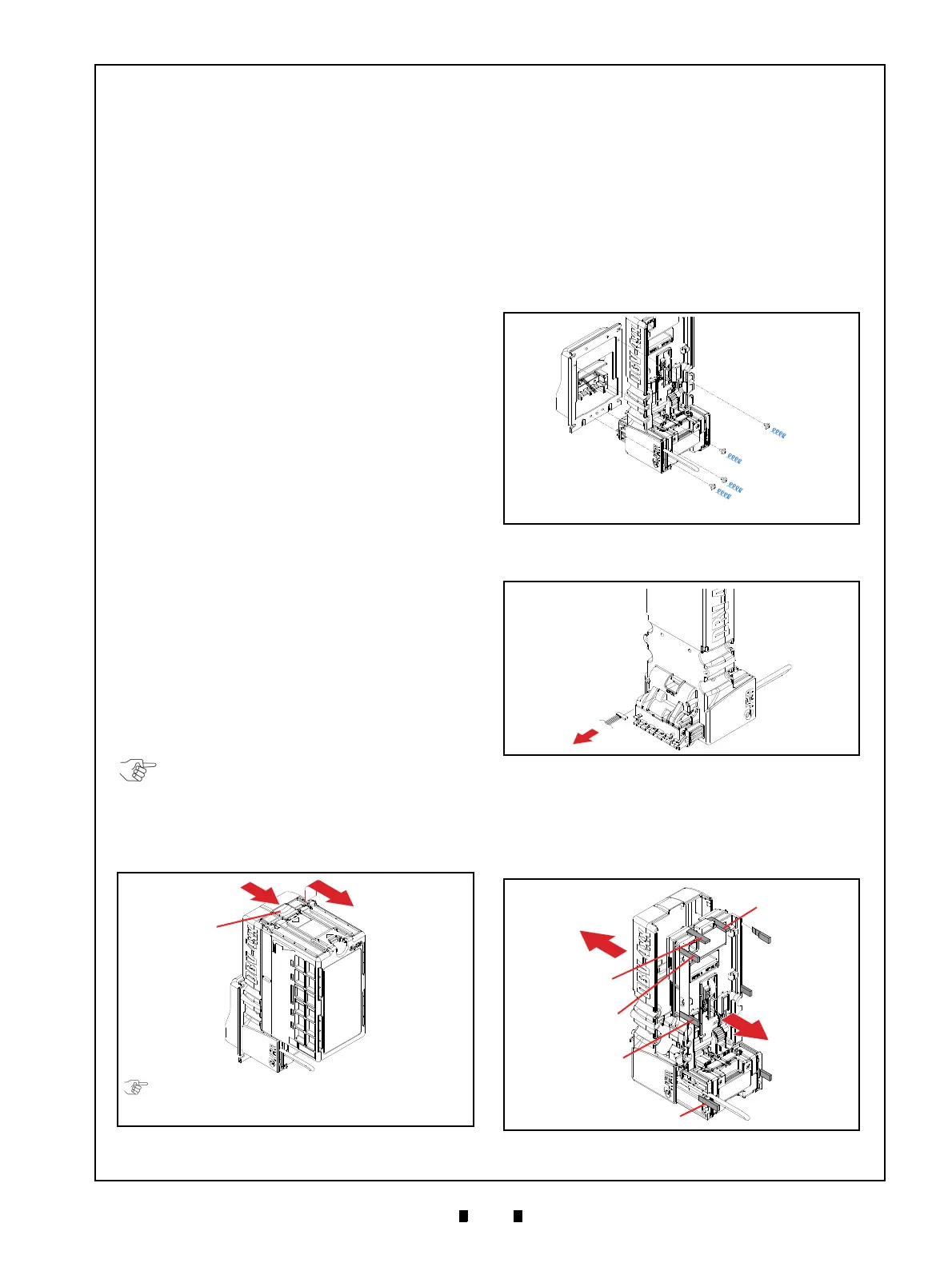
2. Remove the four (4) Mounting Screws (Figure 4-
2 b
1
through b
4
) securing the Bezel Unit (Figure
4-2 a) to the DBV-400 Main Unit. Then remove
the Bezel Unit from the DBV-400 Main Unit.
3. Unplug the single (1) Connector (Figure 4-3 a).
4. Insert the Main Frame Assy. Disassembling Tool
(8 pieces) into the indicated eight (8) spots (Fig-
ure 4-4 a
1
through a
8
). Then remove the Main
Frame Assy. (Figure 4-4 b) from the DBV-400
Frame Cover (Figure 4-4 c).
NOTE: In the case of the optional Rear-
Access Cash Box, pressing the Cash Box
Release Button can be skipped.
Pull the Rear-Access Cash Box upward
and then out in the direction indicated by
the arrow A.
Figure 4-1 Cash Box Removal
Figure 4-1 Cash Box Removal
a
A
The Standard Cash Box and Rear-Access Cash Box
have a blue-colored and black-colored Cash Box
Release Button respectively.
Figure 4-2 Bezel Unit Removal
Figure 4-2 Bezel Unit Removal
Figure 4-3 Unplugging Connector
Figure 4-3 Unplugging Connector
Figure 4-4 Main Frame Assy. Removal
Figure 4-4 Main Frame Assy. Removal