P/N 960-000180R_Rev. 1 {EDP #233427} © 2016, JAPAN CASH MACHINE CO., LTD.
Calibration and Testing DBV® Series DBV-400 Banknote Validator Section 6
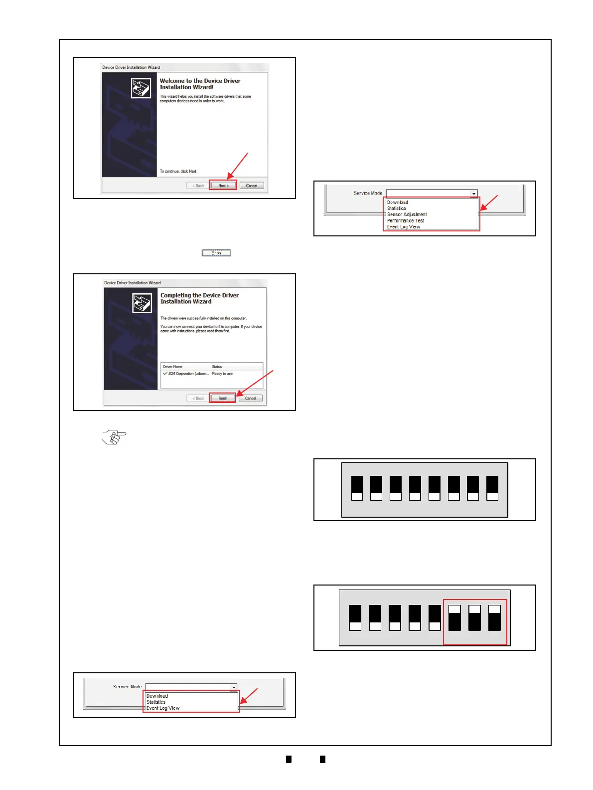
5. When the USB Driver Installation is complete,
the “
Completing the Device Driver Installation
Wizard
” Screen will appear as shown in Figure 6-
10. Click on the “
Finish” Screen Button
(Figure 6-10 a) to close the Screen.
This completes the DBV-400 USB Driver Software
installation procedure.
JCM Tool Suite Standard Edition
Mode
The following two (2) mode feature types exist in
the “
JCM Tool Suite Standard Edition” package:
• Normal Mode
• Test Mode
“Normal Mode” is a mode designed to provide the
DBV-400 Operating Software to be downloaded.
The “
Service Mode” contains three (3) available
choices (shown in Figure 6-11a) as follows:
• Download (for downloading software)
• Statistics (for observing log data)
• Event Log View (for confirming Event Log)
“Test Mode” is a mode designed to perform DBV-
400 Calibration and Performance Testing. The
“
Service Mode” contains five (5) available choices
in its Pull-down Menu (Figure 6-12 a) as follows:
• Download (for downloading software)
• Statistics (for observing log data)
• Sensor Adjustment (for calibration)
• Performance Test (for Performance Testing)
• Event Log View (for confirming Event Log)
Download Procedures
The following two (2) procedures are available to
download the DBV-400 Software Program:
• The DBV-400 Software Program is loaded on the
Unit (Normal)
• The DBV-400 Software Program is not loaded on
the Unit (e.g., after replacing the CPU Board)
Software Program Download
To download the DBV-400 Software Program,
proceed as follows:
1. Remove electrical power from the DBV-400 Unit.
2. When upgrading the Software in Normal
condition, set all of the 8-position DIP Switches
of DIP Switch Block 1 (
DIP SW1) to OFF
(Figure 6-13).
When downloading to a Unit (Software not
previously installed), set DIP Switch Block 1
(
DIP SW1) Switches #6, #7 and #8 to ON
(Figure 6-14).
3. Connect the USB Port on the DBV-400 Unit to
the PC (Refer to Figure 6-1 and Figure 6-2 for
Tool Requirements and Harness Connector loca-
tions).
4. Apply electrical power to the DBV-400 Unit.
Figure 6-9 Hardware Update Wizard Screen 1
Figure 6-9 Hardware Update Wizard Screen 1
Figure 6-10 Hardware Update Wizard Screen 2
Figure 6-10 Hardware Update Wizard Screen 2
NOTE: If the Windows Security Screen
appears, select “Install this Driver Software
(I)” to proceed.
Figure 6-11 Normal Mode Selection
Figure 6-11 Normal Mode Selection
Figure 6-12 Test Mode Selection
Figure 6-12 Test Mode Selection
Figure 6-13 Normal Upgrade Setting
Figure 6-13 Normal Upgrade Setting
Figure 6-14 Initial Download Setting
Figure 6-14 Initial Download Setting