P/N 960-000180R_Rev. 1 {EDP #233427} © 2016, JAPAN CASH MACHINE CO., LTD.
Calibration and Testing DBV® Series DBV-400 Banknote Validator Section 6
Calibration Preparation
Perform the following steps to prepare the DBV-
400 for Sensor Calibration:
1. Remove electrical power from the DBV-400 Unit.
2. Remove the Cash Box from the DBV-400 Unit.
3. Connect the USB Cable to the USB Connector for
maintenance (Refer to Figure 6-1 and Figure 6-2
for the Tool Requirements and Harness Connector
locations).
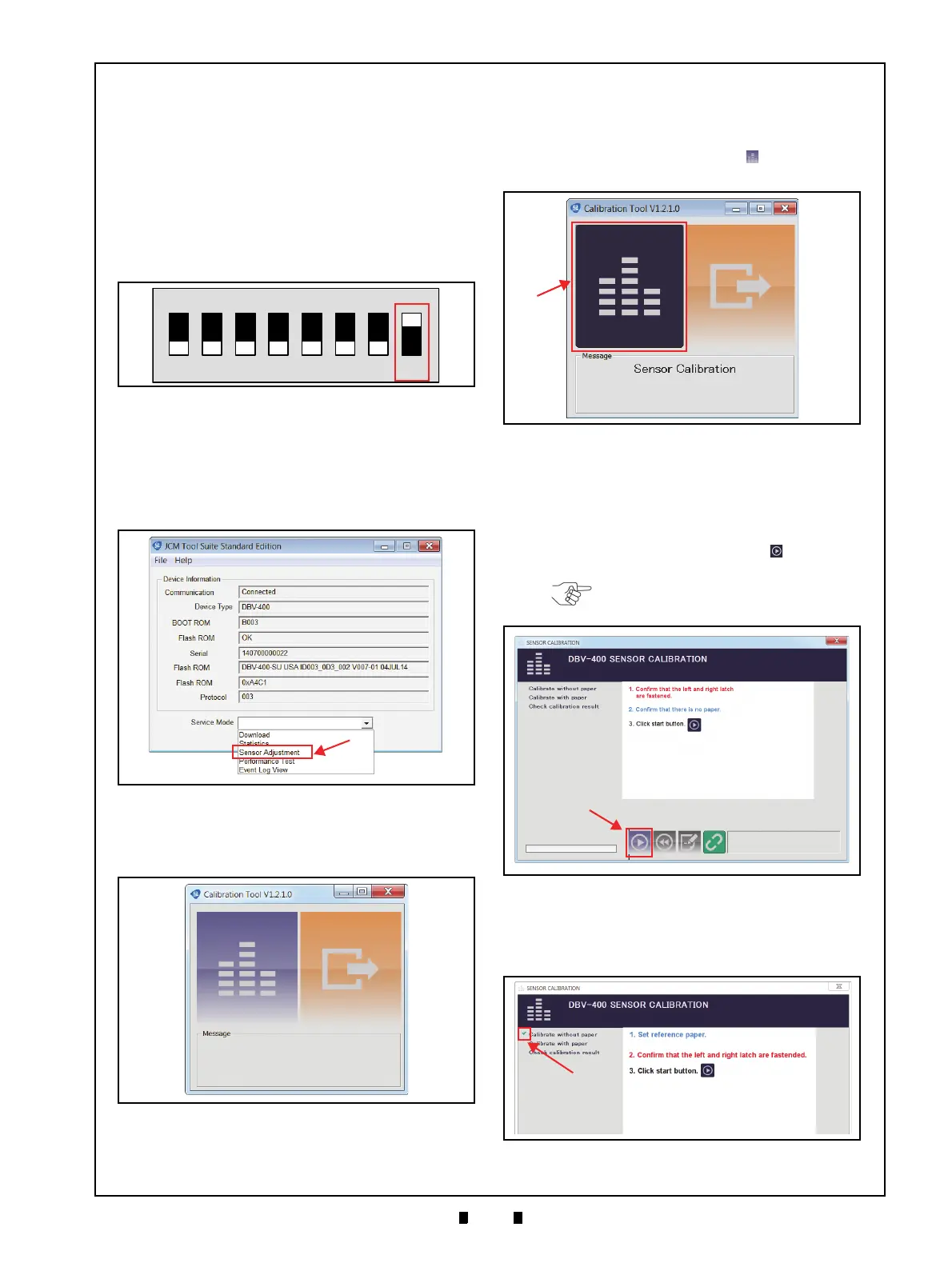
4. Set DIP Switch #8 to
ON (Figure 6-30).
5. Apply electrical power to the DBV-400 Unit. The
Bezel LED will flash a Green color rate.
6. Launch the “
JCM Tool Suite Standard Edition”
Application (Figure 6-31), then click the “
Service
Mode
” Pull-Down Menu, and select “Sensor
Adjustment
” (Figure 6-31 a).
7. Confirm that the Sensor Calibration Program
Screen appears (Figure 6-32).
Sensor Calibration
To calibrate the DBV-400 sensors, proceed as
follows:
1. Click the “Sensor Calibration” button (Figure
6-33 a).
2. Confirm that the “
DBV-400 SENSOR
CALIBRATION
” Screen appears (Figure 6-34).
3. Make sure the Validation Guide Open/Close
Latch (refer to Figure 1-4 n) is Closed (securely
latched in the Down position on both the left and
right sides). Then click the “
Start” button
(Figure 6-34 a) to begin the non-paper calibration.
4. Confirm that the non-paper calibration was
completed with a check mark (Figure 6-35 a)
appearing next to the “
Calibration without paper”
text line.
Figure 6-30 DIP SW1 Setting
Figure 6-30 DIP SW1 Setting
Figure 6-31
Launching JCM Tool Suite Stan-
dard Edition/Sensor Adjustment
Figure 6-31 Launching JCM Tool Suite Standard
Edition/Sensor Adjustment Selection
Figure 6-32 Sensor Calibration Screen 1
Figure 6-32 Sensor Calibration Screen 1
Figure 6-33 Sensor Calibration Screen 2
Figure 6-33 Sensor Calibration Screen 2
NOTE: Make sure there are no
foreign objects in the Transport Path.
Figure 6-34 Non-Paper Calibration Screen
Figure 6-34 Non-Paper Calibration Screen
Figure 6-35 Non-Paper Calibration Com-
Figure 6-35 Non-Paper Calibration Completion