P/N 960-000180R_Rev. 1 {EDP #233427} © 2016, JAPAN CASH MACHINE CO., LTD.
Calibration and Testing DBV® Series DBV-400 Banknote Validator Section 6
Acceptance Test
To perform the Acceptance Test, proceed as
follows:
1. Remove electrical power from the DBV-400 Unit.
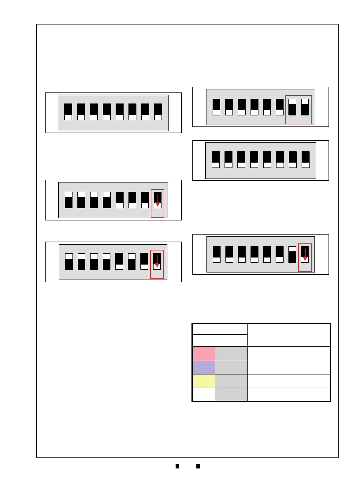
2. Select the desired Acceptance Test by setting the
DIP Switches as indicated in Table 6-4.
3. Set the all DIP SW2 switches to
OFF (Figure 6-
66)
4. Apply electrical power to the DBV-400 Unit and
confirm that the Bezel LED flashes at a Green
color rate.
5. Set the DBV-400 DIP SW1 #8 to
OFF (Figure 6-
67).
6. Place the Cash Box onto the DBV-400 Unit.
7. Confirm that the DBV-400 performs a
initialization and goes to idle, waiting for a
Banknote insertion. If errors occur, refer to
Appendix A Table A-1.
8. Set the DIP SW1 #8 to
ON to end the Acceptance
Test.
This completes the Acceptance Test.
Sensor Test
To perform the Sensor Test, proceed as
follows:
1. Remove electrical power from the DBV-400 Unit.
2. Set the DBV-400 DIP SW1 #7 and #8 to
ON (Fig-
ure 6-69) and the all DIP SW2 switches to
OFF
(Figure 6-70).
3. Apply electrical power to the DBV-400 Unit and
confirm that the Bezel LED flashes at a Green
color rate.
4. Set the DBV-400 DIP SW1 #8 to
OFF (Figure 6-
71) and confirm that the Bezel LED flashes at a
Purple color rate.
5. Perform each Sensor Test (refer to “Test Proce-
dure” in Table 6-6).
6. Confirm that the resulting Bezel LED condition
matches the Bezel LED color stated in Table 6-6.
7. Set the DIP SW1 #8 to
ON to end the Sensor Test.
This completes the Sensor Test.
Figure 6-66 Acceptance Test DIP SW2 Setting
Figure 6-66 Acceptance Test DIP SW2 Setting
Figure 6-67 DIP SW1 #8 OFF For Acceptance
Test With Validation
Figure 6-67 DIP SW1 #8 OFF For Acceptance
Test With Validation
Figure 6-68 DIP SW1 #8 OFF For Acceptance
Test Without Validation
Figure 6-68 DIP SW1 #8 OFF For Acceptance
Test Without Validation
Table 6-6 Sensor Test Procedure and Confirmation
Bezel LED Color State
Test Procedure
*
*. Refer to “DBV-400 Component Names” on page 1-5 and “Sensor and Roller Loca-
tions” on page 2-12 for the component and sensor locations respectively.
Detected Not Detected
Red
Extinguished
Cover/uncover the Entrance Sensor
using a Banknote.
Blue Extinguished
Cover/uncover the Validation Sensor
using a Banknote.
Yellow Extinguished
Cover/uncover the Exit Sensor using
a Banknote.
White
Extinguished
Push down/release the Cash Box DT
Lever.(Box In Sensor).
Figure 6-69 Sensor Test DIP SW1 Setting
Figure 6-69 Sensor Test DIP SW1 Setting
Figure 6-70 Sensor Test DIP SW2 Setting
Figure 6-70 Sensor Test DIP SW2 Setting
Figure 6-71 DIP SW1 #8 OFF
Figure 6-71 DIP SW1 #8 OFF
 Loading...


