P/N 960-000180R_Rev. 1 {EDP #233427} © 2016, JAPAN CASH MACHINE CO., LTD.
Section 6 DBV® Series DBV-400 Banknote Validator Calibration and Testing
Sensor Test
To perform the Sensor Test, proceed as follows:
1. Launch the Main Screen (Refer to “Performance
Test Preparation” on page 6-10).
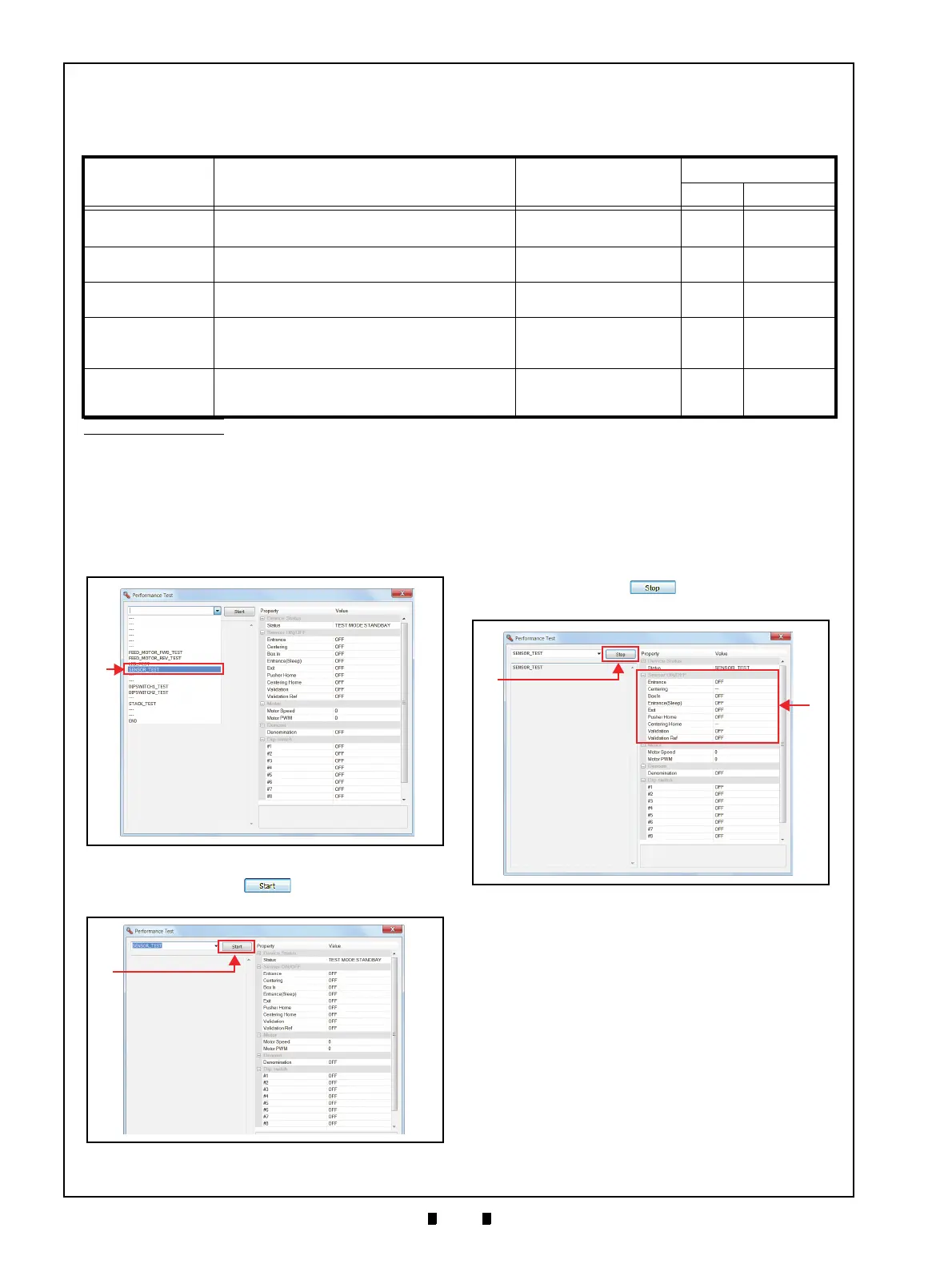
2. Click the “Performance Test” Pull-down Menu
(Figure 6-54 a), and select “SENSOR_TEST”.
3. Click the “
Start” Screen Button (Figure
6-55 a) to begin the test.
4. Perform each Sensor Test
(refer to “Test Procedure” in Table 6-3).
The resulting condition will appear in the “Sensor
ON/OFF” and “Stacker” areas (Figure 6-56 b).
5. Confirm that the resulting condition matches the
action stated in Table 6-3.
6. Click the “
Stop” Screen Button (Figure
6-56 a) to end the test.
Table 6-3 Sensor Test Items
Sensor Names
*
Test Purpose
Test Procedure
PC Screen
Detected NOT Detected
Entrance Sensor
Detects that a Banknote is present at the Entrance
Sensor.
Cover/uncover the Entrance
Sensor using a Banknote.
ON OFF
Box In Sensor
The Box In Sensor detects the presence of a Cash
Box.
Push down/release the
Cash Box DT Lever.
ON OFF
Exit Sensor
Detects that a Banknote is present at the Exit
Sensor.
Cover/uncover the Exit
Sensor using a Banknote.
ON OFF
Pusher Home Sensor
Detects that the Pusher Mechanism is at the Home
Position.
Remove the CPU Circuit
Board and block/unblock
the Pusher Home Sensor.
†
ON OFF
Validation Sensor
(Inside and Outside)
The Outside Sensor detects the presence of a
Banknote.
Cover/uncover the Inside
and/or Outside Validation
Sensor using a Banknote.
ON OFF
*. Refer to “DBV-400 Component Names” on page 1-5 and “Sensor and Roller Locations” on page 2-12 for component and sensor locations respectively.
†. This test is only available with the CPU Circuit Board removed from the Main Frame Assy. Refer to “CPU Circuit Board Removal” on page 4-1 for the CPU Circuit Board
removal.
Five (5) Tests exist within the Sensor Test Menu. Table 6-3 lists each Sensor Test Item function.
Figure 6-54 Sensor Test Selections
Figure 6-54 Sensor Test Selections
Figure 6-55 Sensor Test Screen 1
Figure 6-55 Sensor Test Screen 1
Figure 6-56 Sensor Test Screen 2
Figure 6-56 Sensor Test Screen 2