P/N 960-000180R_Rev. 1 {EDP #233427} © 2016, JAPAN CASH MACHINE CO., LTD.
Section 6 DBV® Series DBV-400 Banknote Validator Calibration and Testing
Push Button Test
To perform the Bezel LED Test, proceed as
follows:
1. Connect the Power Harness and apply electrical
power to the DBV-400 Unit.
2. Confirm that the Bezel LED is lit a steady default
color.
3. Press the PUSH Button (Figure 6-72 a) in the
center until you feel it “click.”
4. Confirm that Bezel LED is lit in the sequential
order as follows: Green -> Cyan -> Blue ->
Magenta -> White-> Gradation.
This completes the Push Button Test.
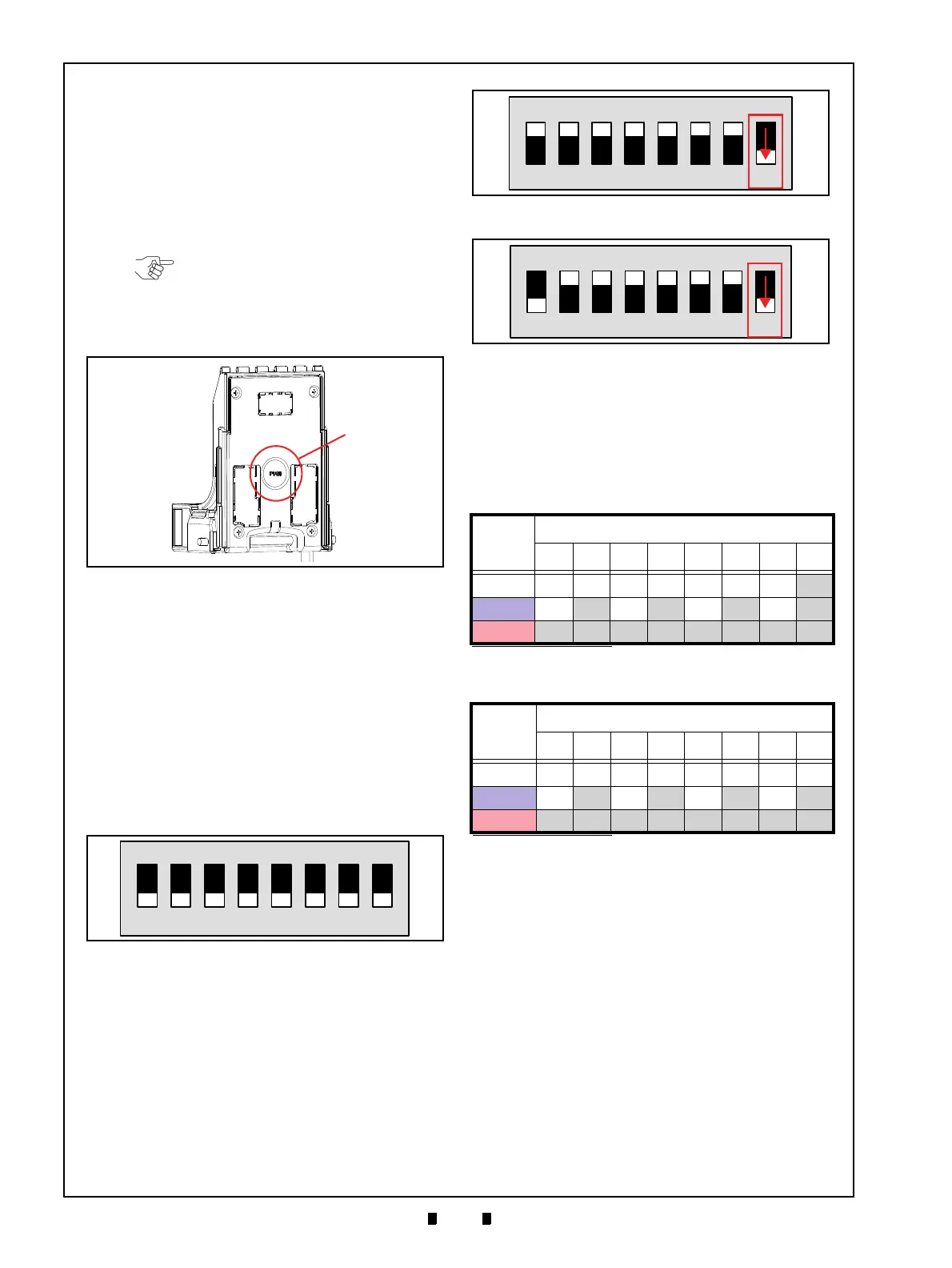
DIP Switch Test
To perform the DIP Switch 1 (SW1) and/or DIP
Switch 2 (SW2) Test, proceed as follows:
1. Remove electrical power from the DBV-400 Unit.
2. Set the DIP SW1 switches for the desired DIP
Switch Test as indicated in Table 6-4.
3. Set the all DIP SW2 switches to
OFF (Figure 6-
73).
4. Apply electrical power to the DBV-400 Unit and
confirm that the Bezel LED flashes at a Green
color rate.
5. Set the DBV-400 DIP SW1 #8 to
OFF
(Figure 6-74 for DS1 Testing or Figure 6-75 for
DS2 Testing respectively) and confirm the Bezel
LED flashes at a Purple color rate.
6. Set the switches on DIP SW1 or DIP SW2 ON or
OFF as shown in Table 6-7 and Table 6-8.
7. Confirm that the resulting Bezel LED condition
matches the color stated in Table 6-7 for DIP
Switch 1Test Confirmation and Table 6-8 for DIP
Switch 2 Test Confirmation.
8. Set the DIP SW1 #8 to
ON to end the DIP Switch
Test.
This completes the DIP Switch Test.
NOTE: Pressing the Push Button too
hard may cause damage to the
Button. Press the center of the
Button slowly and hold it down until
“click feeling” can be felt.
Figure 6-72 Push Button Location
Figure 6-72 Push Button Location
Figure 6-73 DIP Switch Test DIP SW2 Setting
Figure 6-73 DIP Switch Test DIP SW2 Setting
Table 6-7 DIP Switch 1 Test Confirmation
Bezel
LED
Color
*
*. The Bezel LED is extinguished when the DIP Switches are set to settings not listed
in Table 6-7.
DIP Switch 1 Setting
12345678
White ONONONONONONON -
Blue
ON
OFF
ON
OFF
ON
OFF
ON
-
Red OFF OFF OFF OFF OFF OFF OFF -
Table 6-8 DIP Switch 2 Test Confirmation
Bezel
LED
Color
*
*. The Bezel LED is extinguished when the DIP Switches are set to settings not
listed in Table 6-8.
DIP Switch 2 Setting
12345678
White ONONONONONONONON
Blue
ON
OFF
ON
OFF
ON
OFF
ON
OFF
Red OFF OFF OFF OFF OFF OFF OFF OFF
Figure 6-74 DIP SW1 #8 OFF for DS1 Testing
Figure 6-74 DIP SW1 #8 OFF for DS1 Testing
Figure 6-75 DIP SW1 #8 OFF for DS2 Testing
Figure 6-75 DIP SW1 #8 OFF for DS2 Testing