P/N 960-000180R_Rev. 1 {EDP #233427} © 2016, JAPAN CASH MACHINE CO., LTD.
DBV® Series
DBV-400 Banknote Validator
Section 6
This section provides Calibration and Performance
Testing instructions for the DBV
®
Series DBV-400
Banknote Validator Unit and contains the following
information:
• Tool Requirement
• Installation Procedures
• JCM Tool Suite Standard Edition Mode
• Download Procedures
• Calibration
• Performance Tests
Tool Requirement
See “Component Names” on page 1-5 for detail
connector locations.
Workbench Tool Requirements With
Reference Paper and a PC
Figure 6-1 and Figure 6-2 identify the Tools and
equipment interconnects necessary to install and/or
download the Application Software, USB driver
and Firmware Software, to calibrate the DBV-400
Unit away from its Host Machine, and to perform a
DBV-400 Performance Test using a PC.
Workbench Tool Requirements
Without a PC
Figure 6-3 identifies the Tools and equipment
interconnects necessary to perform a DBV-400
Performance Test without a PC.
Power Supply
Either a 12 - 24V DC Power Supply for DBV-400
Series Units or a UAC Converter is required to per-
form the following procedures:
• Sensor Calibration
• Downloading Software to Flash Memory
• Communication between the DBV-400 Unit
and the PC
Installation Procedures
This section provides the JCM Tool Suite Standard
Edition installation procedure.
Application Software Installation
Perform the following steps to install the “JCM Tool
Suite Standard Edition
” Application Software
(Refer to Figure 6-1 “Tool and Harness Connec-
tions 1” and Figure 6-2 “USB Cable Type Require-
ment” for tool requirement).
1. Copy the “JCMToolSuiteStandardEdition.zip”
Application Software and extract it onto the
Desktop.
6 CALIBRATION AND TESTING
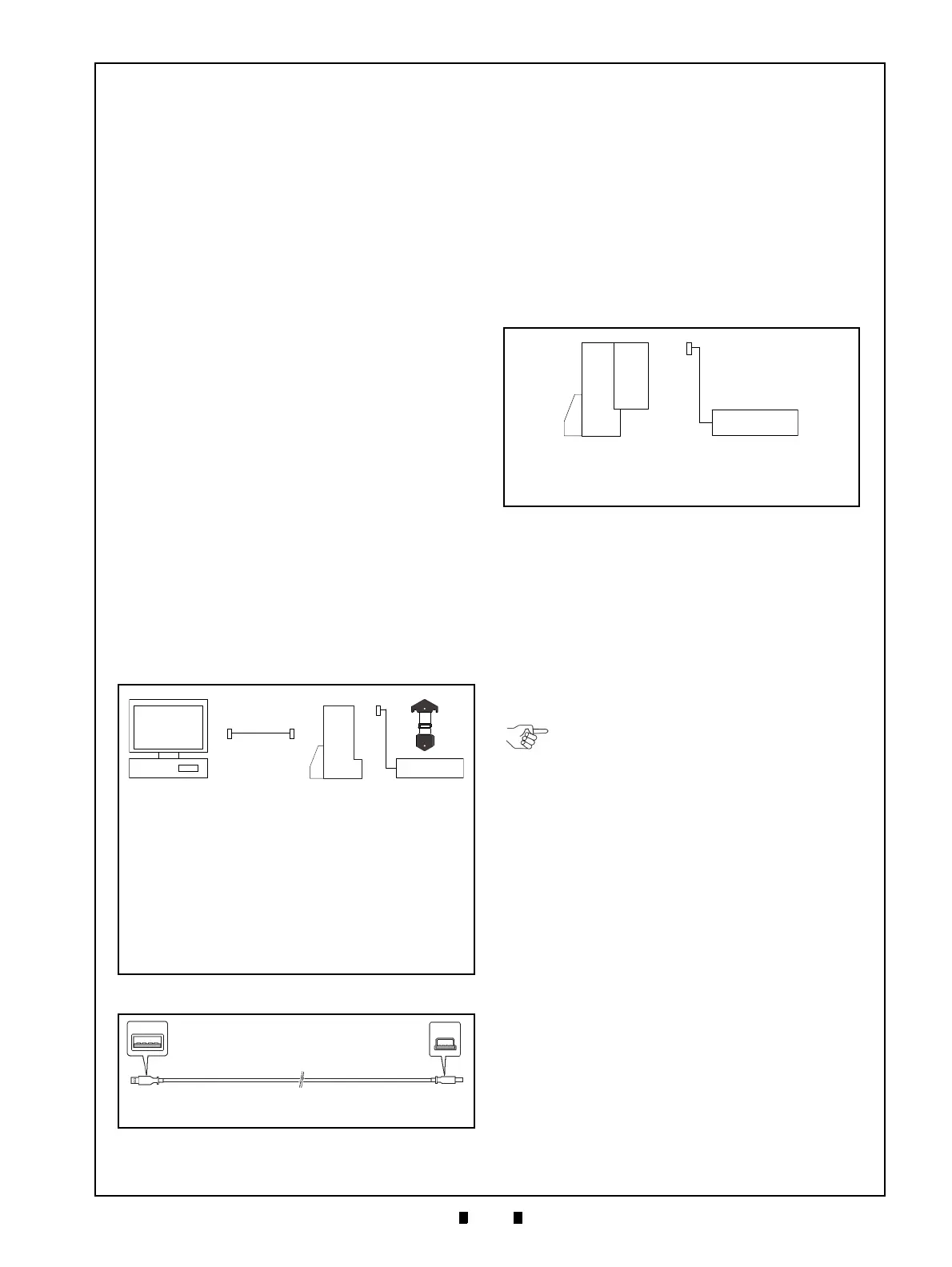
Figure 6-1 Tool and Harness Connections 1
Figure 6-1 Tool and Harness Connections 1
a) DBV-400 Device without Cash Box
b) Power Supply
c) PC (OS: Windows XP/7)
(DBV-400 Driver Installed)
d) USB Cable
d
1
) USB “A” Terminal Plug
d
2
) USB Mini “B” Terminal Plug
e) Application Software*
(JCM Tool Suite Standard Edition)
f) Reference Paper (KS-095A)
*. Containing USB Downloader, Sensor Calibration, Performance
Test programs and Utility Function.
a
b
d
d
1
d
2
e
c
f
Figure 6-2 USB Cable Type Requirement
Figure 6-2 USB Cable Type Requirement
a) PC Side (USB A Terminal)
b) DBV-400 Side (USB Mini-B Terminal)
a
b
Figure 6-3 Tool and Harness Connections 2
Figure 6-3 Tool and Harness Connections 2
a) DBV-400 with Cash Box
(DBV-400 Firmware Software installed)
b) Power Supply
If the UAC Converter shown in Table A-6 on
page A-8 is preferred, refer to JCM UAC
Device Operational Instructions (Part No.
960-100194R) for details on its use.